Language selection
В настоящее время портал работает - ведутся технические работы.
Catalog

TEKHNOYAKS
61 products
View:
Telephone number:
E-mail:
mail@tehnojaks.ru
Website: https://tehnojaks.com
Address:
Russia, Moscow, 30
Website: https://tehnojaks.com
Address:
Russia, Moscow, 30
- Selected: 0Areas of use
- Selected: 0Item names
- Selected: 0Manufacturer
- Selected: 0Made in
- Selected: 0Additional
View:
51 products
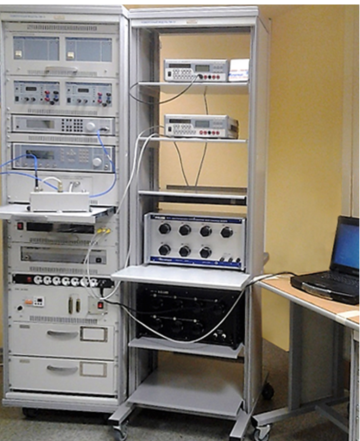
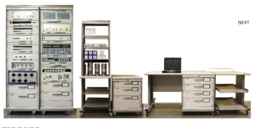
Verification module PM-10
The composition of the PM-10 verification module:
Wattmeter of passing power M2-35;
Complex transmission and reflection coefficients meter "OBZOR-804/1";
Universal voltmeter V7-81 (2 pcs.);
High-frequency signal generator G4-229;
High-frequency signal generator G4-230;
DC power supply B5-79/1 (2 pcs.);
AC power source B2-7 (2 pcs.);
The measure of DC electrical resistance is multi-valued MS3070-3, CT 0.005;
The measure of DC electrical resistance is multi-valued MS3055, CT 0.02;
Single-digit electrical resistance measures MS3080 (0.1; 1 ohm, CT 0.005);
Thermoelectric voltage converter 0.5 V;
Kit for measuring coaxial connectors KISK-7M;
PC, printer;
Basic load-bearing structures (BNC).
Technical specifications
Measuring ranges of electrical and radio engineering quantities:
Operating frequency range from 0.03 to 17.85 GHz
Passing microwave power from 0.01 to 10 MW
VSWR of the microwave tract from 1.05 to 3
Constant electrical voltage from 10 MV to 1000 V
Alternating electric voltage from 1 mV to 750 V
Thermoelectric voltage comparison from 0.1 to 0.5 V
Ranges of reproduction of electrical quantities:
Constant electrical voltage from 1 to 120 V
Resistance to direct electric current from 0.01 to 122222.21 ohms
Measurement errors of electrical and radio engineering quantities:
Passing microwave power ± (1.5 - 2.3) %
VSWR of the microwave path ± (4,15 – 10) %
Constant electrical voltage ± (0.003 – 20) %
Alternating electric voltage ± (0.09 - 15) %
Thermoelectric voltage comparison ± (0.01 – 0.1) %
Errors in the reproduction of electrical quantities:
Constant electrical voltage ± (100 – 200) mV
Resistance to direct electric current CT 0.005; 0.02
General technical characteristics:
The area occupied by the module is 4 – 8 m2
Weight, not more than 340 kg
Power supply voltage from 198 to 242 V with a frequency of (50 ± 0.5) Hz
Power consumption, not more than 2000 VA
TEKHNOYAKS
Moscow
Produced in: Moscow
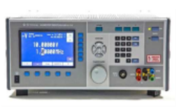
Universal calibrator H4-24
The main field of application of the calibrator is the verification of measuring instruments.
The calibrator is capable of operating both independently and as part of automated measuring systems with interfaces such as USB, RS-232, IEEE-488 and ETHERNET.
Technical specifications
Ranges of reproduction of electrical quantities:
- constant electrical voltage from 0 to 1000 V
- alternating electric voltage in the frequency range from 10 Hz to 70 kHz from 0.9 mV to 1050 V
- alternating electric voltage in the frequency range up to 100 kHz up to 750 V
- alternating electrical voltage in the frequency range up to 1 MHz to 110 V
- the power of direct electric current from 0 to 2 A
- the power of alternating electric current in the frequency range from 10 Hz to 10 kHz from 0.9 µA to 2 A
- electrical resistance of 1, 10, 100 ohms, 1,10,100 kOhm, 1,10,100 mOhm
Errors in the reproduction of electrical quantities:
- constant electrical voltage ± (0.0012 – 0.003)% of U + (0.0003 – 0.015)% of
Up - alternating electric voltage in the frequency range from 10 Hz to 1 MHz ± (0.007 – 0.3)% of U + (0.001 – 0.25)% of
Up - DC current ± (0.004 – 0.007)% of I + (0.001 – 0.01)% of
Ip - AC electric current in the frequency range from 10 Hz to 10 kHz ± (0.015 – 0.1)% of I + (0.002 – 0.1)% of
Ip - electrical resistance ± (0.002 – 0.005)%
General characteristics:
Operating temperature range from 5 to 40 °C
AC power supply 220 V, 50 Hz
Power consumption, no more than 500 VA
Overall dimensions, mm 480x200x550
Weight, not more than 35 kg
TEKHNOYAKS
Moscow
Produced in: Moscow
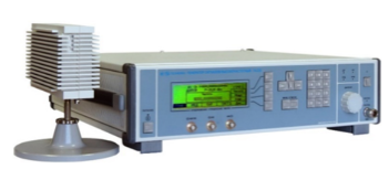
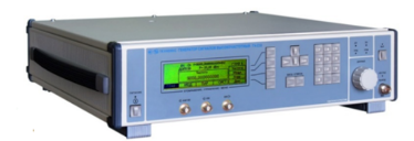
High-frequency signal generator G4-232
A remote frequency converter with coaxial output extends the frequency range up to 37.5 GHz. The included coaxial-waveguide transitions and the ability to connect a small frequency converter directly to the user's device expand the scope of the device.
The generator is capable of operating both independently and as part of automated measuring systems with USB and IEEE-488 (CPC) interfaces.
Technical specifications
The frequency range at the output of the base unit is from 5 to 20 GHz
The frequency range at the output of the frequency converter is from 5 to 37.5 GHz
Frequency tuning discreteness 0.001 Hz
The main error of the frequency setting is ± 3x10⁻⁷ Hz
The range of setting the signal power level at the output of the base unit is from minus 110 to 13 dBm
The range of setting the signal power level at the output of the frequency converter is from 0 to 13 dBm
The basic error of setting the reference power level is ± (1.0 – 2.0) dB
Metrological characteristics of the generator in the FM operation mode:
- frequency range of the modulating signal:
LF from 1 Hz to 20 kHz
RF from 10 Hz to 100 kHz
- frequency deviation setting range (taking into account the carrier frequency value):
LF from 1 Hz to 200 kHz
RF from 10 Hz to 10000 kHz
- the main error of the frequency deviation setting is ± (5 – 18)%
Metrological characteristics of the generator in AM operation mode:
- frequency range of the modulating signal from 0.05 to 5.0 kHz
- the range of setting the amplitude modulation coefficient from 1 to 50 %
- the basic error of setting the amplitude modulation coefficient:
internal ± (0.15 M + 0.2)%
external ± (0.20 M + 0.5)%
Metrological characteristics of the generator in the IM operation mode:
- the duration range of modulating pulses from 100 ns to 20 s
- the range of the modulating pulse repetition period from 140 ns to 30 s
- the difference in the duration of the output RF pulses from the duration of the modulating pulses ± 100 ns
Operating temperature range from minus 10°C to 40 °C
AC power supply 220 V, 50 Hz
Power consumption, no more than 150 VA
Overall dimensions, mm 498x136x487
Weight, not more than 20 kg
TEKHNOYAKS
Moscow
Produced in: Moscow
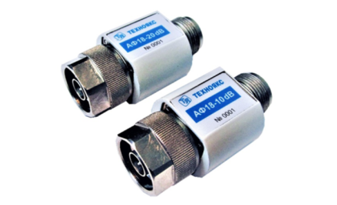
AF18-20dB
Basic properties
Wide frequency range;
Small VSWR values.
Operating conditions
Operating temperature range from minus 10 to 50 ° C;
The relative humidity of the air is up to 98% at a temperature of 25 ° C.
Technical specifications
Nominal attenuation, 20 dB
Attenuation error, dB ± 1.0
VSWR 1.4
Frequency range, GHz 0-18
Input power, W 1
Type of coaxial connectors (according to GOST RV 51914-2002) IIIB-IIIP
TEKHNOYAKS
Moscow
Produced in: Moscow
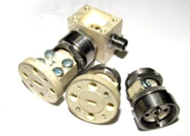
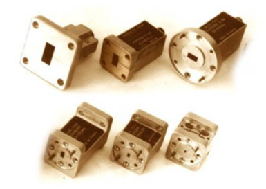
PS-78 (waves.)
Strobe converters are used as input devices of radio measuring equipment: amplifasometers, frequency meters, spectrum analyzers, circuit analyzers, etc.; in systems of synchronization and frequency stabilization of microwave generators, heterodynes, frequency synthesizers.
Basic properties:
Wide frequency range;
Minimal losses and uneven conversion;
High "decoupling" of channels;
Large dynamic range of input signals;
Harsh operating conditions
Operating conditions
Operating temperature range from minus 10 to 50 °C;
Relative humidity up to 98% at a temperature of 25 ° C.
Technical specifications
Frequency range:
• Microwave signal, GHz 37.5-78.33
• heterodyne, GHz 2.0-6.0
• IF, MHz 0-1000
Conversion losses *>, 30-40 dB by the 20th garm.
The power level of the heterodyne, dBm 20-22
Connector type:
• Microwave signal input P-waveguide with transitions to 5,2x2,6 and 3,6x1,8 mm
• 1HR heterodyne input
• IF output two woofer inputs
TEKHNOYAKS
Moscow
Produced in: Moscow

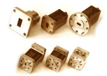
VD-7.2×3.4
A flexible waveguide is a piece of high-quality dielectric, which ends with transitions to standard waveguides with flanges.
For ease of operation, the waveguide is protected by an elastic shell.
Basic properties
Manufacturability of the connection;
Small losses and VSWR;
Economy.
Operating conditions
Operating temperature range from 5 to 50 ° C;
The relative humidity of the air is up to 98% at a temperature of 25 ° C.
Technical specifications
Waveguide cross section, mm 7.2×3.4
Flange type according to GOST RV 51914-2002
Frequency range, GHz 25.95-37.50
VSWR 1.25
Losses, dB 2.0
Length, mm* 500
TEKHNOYAKS
Moscow
Produced in: Moscow
High-frequency signal generator G4-230
The generator is capable of operating both autonomously and as part of automated measuring systems with USB and IEEE-488 (CPC) interfaces.
Technical specifications
Frequency range from 5 to 17.85 GHz
Frequency tuning discreteness 0.001 Hz
The main error of the frequency setting is ± 3x10⁻⁷ Hz
The range of setting the output signal power level at the main output is from minus 110 to 13 dBm
The basic error of setting the reference power level is ± 1.0 dB
Instability of the output signal power level for any 15-minute time interval of no more than 0.1 dB
Metrological characteristics of the generator in the FM operation mode:
- frequency range of the modulating signal:
low frequency from 1 Hz to 20 kHz
RFM from 10 to 100 kHz
- frequency deviation setting range (taking into account the carrier frequency value):
low frequency from 1 Hz to 100 kHz
RFM from 50 to 10000 kHz
- the main error of the frequency deviation setting is ± (3 – 18)%
Metrological characteristics of the generator in AM operation mode:
- frequency range of the modulating signal from 0.05 to 5.0 kHz
- the range of setting the amplitude modulation coefficient from 1 to 50 %
- the main error in setting the amplitude modulation coefficient:
Internal ± (0.15M + 0.2)%
External ± (0.20M + 0.5)%
Metrological characteristics of the generator in the IM operation mode:
- the duration range of modulating pulses from 100 ns to 20 s
- the range of the modulating pulse repetition period from 140 ns to 30 s
- the difference in the duration of the output RF pulses from the duration of the modulating pulses ± 100 ns
Operating temperature range from minus 10 to 40 °C
AC power supply 220 V, 50 Hz
Power consumption, no more than 150 VA
Overall dimensions, mm 498x136x487
Weight, not more than 15 kg
TEKHNOYAKS
Moscow
Produced in: Moscow
UCHX2-37
Basic properties:
Wide frequency range;
Sufficiently large output power;
High level of suppression of side harmonics of the input signal;
Low value of phase noise;
Relatively simple technical solutions:
- synchronization and frequency stabilization,
- stabilization and adjustment of the output power level,
- implementation of amplitude and frequency modulation modes;
Do not require external bias diodes.
Operating conditions:
Operating temperature range from minus 10 to 50 ° C;
The relative humidity of the air is up to 98% at a temperature of 25 ° C.
Technical characteristics
Input/output frequency range, GHz 12,93-18,75 / 25,86-37,5
Losses (max.), dB 13
Input power level, dBm 15-21
Unevenness of output power (Rvh. = 20 dBm), dB ± 1.5
The level of parasitic harmonics of the input signal at the output (min.), dBn 20
Output VSWR (max.) 2.0
Connector type:
• Input Coax. 3.5/1.5 mm (socket)
• Output Waveguide 7.2x3.4 mm
Overall dimensions, mm 29x24x24
Weight, g 60
TEKHNOYAKS
Moscow
Produced in: Moscow
Verification module PM-9
The composition of the PM-9 calibration module:
Universal voltmeter calibrator H4-12 (2 pcs.);
Variable voltage calibrator H5-5A;
A measure of the stress ratio H4-8;
AC voltage voltmeter VK3-78A;
Generator-calibrator of harmonic signals SK6-122;
The meter-calibrator of the harmonic coefficient SK6-20A;
AC power source B2-7 (2 pcs.);
The measure of DC electrical resistance is multi-valued MS3070-2;
The measure of DC electrical resistance is multi-valued MS3055;
Decadal high-resistance resistance magazine M-109R;
Single-digit electrical resistance measures MS3080 (0.001; 0.01; 0.1 ohms);
Electrical resistance measures unambiguous MS3050M (1, 10, 100, 1000, 10000, 100000 Om);
The measure of electrical resistance is unambiguous P4013;
The measure of electrical resistance is unambiguous P4023;
The measure of electrical resistance is unambiguous P4033;
PC, printer;
Basic load-bearing structures (BNC).
Technical specifications
Measuring ranges of electrical quantities:
Constant electrical voltage DC from 1 MV to 1000 V
AC alternating electric voltage in the frequency range of 10 Hz ... 1 MHz from 10 mV to 1000 V
Alternating electric voltage high-frequency VRF in the frequency range of 10 Hz ... 2000 MHz from 10 mV to 100 V
Harmonic coefficient in the frequency range of 10 Hz ... 200 kHz from 0.001 to 100 %
Ranges of reproduction of electrical quantities:
Constant electrical voltage DC from 1 nV to 1000 V
AC alternating electric voltage in the frequency range of 10 Hz ... 1 MHz from 3 MV to 1000 V
Alternating electric voltage high-frequency VRF in the frequency range of 1 MHz ... 2000 MHz from 3 MV to 3 V
DC electric current from 1 µA to 20 A
The power of alternating electric current in the frequency range from 0.1 Hz to 10 kHz from 1 µA to 20 A
Electrical resistance from 0.001 ohms to 11
ohms Harmonic coefficient in the frequency range from 10 Hz to 200 kHz from 0.001 to 100 %
Measurement errors of electrical quantities:
Constant electrical voltage DC ± (0.0011 ... 4.0) %
AC alternating electric voltage, in the frequency range 10 Hz ... 1 MHz ± (0.0055 ... 1.2) %
Alternating electric voltage high-frequency VRF in the frequency range 1 MHz ... 2000 MHz ± (0.2 ... 6.0) %
Harmonic coefficient in the frequency range from 10 Hz to 200 kHz ± (0.0008 ... 2.0) %
Errors in the reproduction of electrical quantities:
Constant electrical voltage DC ± (0.0011 ... 4.0) %
AC alternating electric voltage in the frequency range 10 Hz ... 1 MHz ± (0.0055 ... 4.0) %
Alternating electric voltage high-frequency VRF in the frequency range 1 MHz ... 2000 MHz ± (0.6 ... 10.0) %
DC power ± (0.0033 ... 0.5) %
The power of alternating electric current in the frequency range from 10 Hz to 10 kHz ± (0.055 ... 1.0) %
Electrical resistance ± (0.001 ... 1.0) %
Harmonic coefficient in the frequency range from 10 Hz to 200 kHz ± (0.006 ... 2.0) %
General technical characteristics:
The area occupied by the module is 6-12 m2
Weight, not more than 430 kg
Power supply voltage from 198 to 242 V with a frequency of (50 ± 0.5) Hz
Power consumption, no more than 2000 VA
TEKHNOYAKS
Moscow
Produced in: Moscow
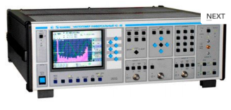
Universal frequency meter Ch3-89
The frequency meter is able to work both independently and as part of automated measuring systems with interfaces such as USB or RS-232.
Technical specifications
Frequency and period of sinusoidal signals (inputs A, B) 0.001 Hz - 150 MHz
Frequency of video pulse signals (inputs A, B) 0.001 Hz - 100 MHz
Frequency of continuous sinusoidal oscillations (input C) (0.1 - 1) GHz
Frequency of continuous sinusoidal oscillations (input D) (1 - 37.5) GHz
Carrier frequency of a continuous signal with frequency modulation (FM) (input D) Fh = (1 - 18) GHz, Fm = 100 Hz-100 kHz; frequency deviation from 10 kHz to 10 MHz
Carrier frequency of a continuous signal with amplitude modulation (AM) (input D) Fh = (1 - 18) GHz, Fm = 100 Hz - 100 kHz; AM factor up to 100%
Carrier frequency of a continuous radio pulse sequence (IM) signal (input D) Fn = (1-37.5) GHz, from 0.15 microseconds to 1ms, Fsl from 100 Hz to 3 MHz, from 2 to 103
Pulse duration 10 ns – 0.1 s
Time interval from -10 to 10 s
The duration of the front, the decay of the pulses is 5 ns - 100 microseconds
Phase difference of two synchronous sinusoidal signals from minus 360° to 360°
The measurement error of the phase difference of two synchronous sinusoidal signals is ± 0.36° (from 1 kHz to 1 MHz) ± 3.6° (above 1 MHz)
Input signal level:
•for sinusoidal signal (inputs A, B) (0.03 - 7.0) V
•for video pulse signal (inputs A, B) (0.1 - 10.0) V
•for a sinusoidal signal (input C) (0.03 - 1.0) V
•for sinusoidal and IM signals (input D) 10 MW (from 1 to 8 GHz); 40 MW (sv. 8 to 18 GHz); 50 MW (sv. 18 to 37.5 GHz).
The nominal frequency value of the reference quartz oscillator is 10 MHz
Relative error in the frequency of the quartz oscillator, no more than ± 2x10⁻⁷ in 12 months
Operating temperature range from 5 to 40 °C
AC power supply 220 V, 50 Hz
Power consumption, no more than 100 VhA
Overall dimensions, mm 496x174x459
Weight, not more than 16 kg
TEKHNOYAKS
Moscow
Produced in: Moscow
UCHX3-53
Basic properties:
Wide frequency range;
Sufficiently large output power;
High level of suppression of side harmonics of the input signal;
Low phase noise value;
Relatively simple technical solutions:
- synchronization and frequency stabilization,
- stabilization and adjustment of the output power level,
- implementation of amplitude and frequency modulation modes;
Do not require external bias diodes.
Operating conditions:
Operating temperature range from minus 10 to 50 °C;
The relative humidity of the air is up to 98% at a temperature of 25 ° C.
Technical characteristics
Input/output frequency range, GHz 12,50- 17,86 / 37,50- 53,57
Losses (max.), dB 17
Input power level, 15-20 dBm
Unevenness of output power (Rvh. = 20 dBm), dB ± 2.0
The level of parasitic harmonics of the input signal at the output (min.), dBn 20
Output VSWR (max.) 2.0
Connector type:
• Input Coax. 3.5/1.5 mm (socket)
• Output Waveguide 5,2x2,6 mm
Overall dimensions, mm 34x20x20
Weight, g 60
TEKHNOYAKS
Moscow
Produced in: Moscow
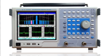
Spectrum Analyzer SK4-105
The spectrum analyzer is capable of working both independently and as part of automated measuring systems with USB and ETHERNET interfaces.
Technical specifications
Frequency range from 9 kHz to 20 GHz
The basic error of frequency measurement is ± (3-10'7hG + 0.2 Hz)
Viewing bands 0; 10 Hz - 20 GHz
Bandwidth minus 3 dB from 1 Hz to 8 MHz
Self-noise level from minus 156 to 145 dB MW/Hz
The basic level measurement error is ± (1.2-1.8) dB
The relative level of interference caused by intermodulation distortions of the 3rd order from minus 50 to 65 dB
The relative level of interference caused by combination distortions from minus 60 to 80 dB
Amplitude scales linear, quadratic, logarithmic (0.1- 20) dB/div
The frequency range of the tracking generator is from 1 MHz to 8 GHz
Operating temperature range from 5 to 40 °C
AC power supply 220 V, 50 Hz
Power consumption, no more than 85 VA
Overall dimensions, mm 420x213x172
Weight, not more than 8 kg
TEKHNOYAKS
Moscow
Produced in: Moscow