Catalog

TEKHNOYAKS
61 products
View:
Telephone number:
E-mail:
mail@tehnojaks.ru
Website: https://tehnojaks.com
Address:
Russia, Moscow, 30
Website: https://tehnojaks.com
Address:
Russia, Moscow, 30
- Selected: 0Areas of use
- Selected: 0Item names
- Selected: 0Manufacturer
- Selected: 0Made in
- Selected: 0Additional
View:
51 products
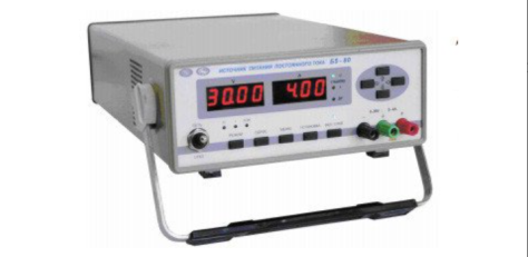
DC power supply B5-80 (81, 82)
The devices are used both independently and as part of automated
systems when working with control from a PC via the RS 232; RS 485 interface.
Technical specifications
Operating temperature range from 5 to 40 °C
AC power supply 220 V, 50 Hz
Power consumption, no more than 400 VA
Overall dimensions, mm 266x105x398
Weight, not more than 8 kg
TEKHNOYAKS
Moscow
Produced in: Moscow
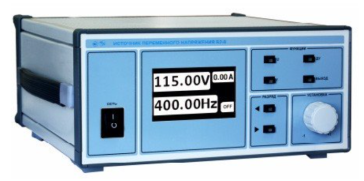
AC voltage source B2-9
The source is capable of operating both independently and as part of automated measuring systems with interfaces such as RS-232 and ETHERNET.
Technical specifications
Output voltage setting range (SCR) from 25 to 250 V
The discreteness of the output voltage setting is 0.05 V
The frequency setting range of the output voltage is from 40 to 500 Hz
The discreteness of the output voltage frequency setting is 0.05 Hz
Output electrical power, not less than 1000 VA
The basic error of setting the output voltage is ± (0.005 Uv + 0.5 V)
The basic error of setting the output voltage frequency is ± 0.1 Hz
Additional error in setting the output voltage caused by a change in the load current from the maximum value to zero ± 0.5 V
Instability of the output voltage for any 10 minutes during 8 hours of continuous operation, no more than ± 0.5 V
Operating temperature range from minus 10 to 50 °C
AC power supply 220 V, 50 Hz
Power consumption, no more than 1300 VA
Overall dimensions, mm 343x160x352
Weight, not more than 6.5 kg
TEKHNOYAKS
Moscow
Produced in: Moscow
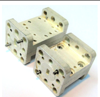
FNCH-45
Basic properties
Low bandwidth losses;
A wide barrage strip.
Operating conditions
Operating temperature range from minus 10
up to 50 ° C;
The relative humidity of the air is up to 98% at a temperature of 25 ° C.
Technical specifications
Waveguide cross section, mm 5.2×2.6
Bandwidth Fh-Fb at the level of -1 dB, GHz 37-45
The barrage band at the level of -30 dB, GHz 50-70
Bandwidth loss, 0.5-1.0 dB
TEKHNOYAKS
Moscow
Produced in: Moscow
Device for measuring attenuation DC1-28
The device is capable of operating both independently and as part of automated measuring systems with USB and IEEE-488 interfaces (CPC).
Technical specifications
Frequency range from 100 kHz to 37.5 GHz
VSWR input of the device with a matching fixed attenuator attenuation of 10 dB, depending on the frequency range, no more
• from 100 kHz to 180 MHz 1.15
• from 0.18 to 2 GHz 1.25
• from 2 to 12 GHz 1.30
• from 12 to 17.85 GHz 1.50
• from 17.85 to 37.5 GHz 2.00
Operating temperature range from 5 to 40 °C
AC power supply 220 V, 50 Hz
Power consumption, no more than 125 VA
Overall dimensions, mm 216x493x508.5
Weight, not more than 32 kg
TEKHNOYAKS
Moscow
Produced in: Moscow
PKV-IP-11×5.5
Basic properties
Wide frequency range;
Small VSWR values.
Operating conditions
Operating temperature range from minus 10 to 50 ° C;
The relative humidity of the air is up to 98% at a temperature of 25 ° C.
Technical specifications
the length of the waveguide, mm 11×5.5
Type of coaxial connector (according to GOST RV 51914-2002) IP
Frequency range, GHz 17.44-25.96
VSWR 1.25
TEKHNOYAKS
Moscow
Produced in: Moscow
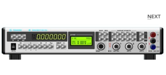
AC voltage voltmeter VK3-78A
The voltmeter is capable of working both independently and as part of automated measuring systems with interfaces such as USB, RS-232, IEEE-488 (CPC).
Technical specifications
Measuring ranges of electrical quantities:
- constant electrical voltage from 3 MV to 1000 V
- SCR of alternating electric voltage in the frequency range from 10 Hz to 1 MHz (AC) from 10 MV to 1000 V
- RF RF AC voltage in the frequency range from 10 Hz to 2000 MHz (RF) from 10 mV to 100 V
- frequency of the measured AC voltage from 10 Hz to 1 MHz
Measurement errors of electrical quantities:
- constant electrical voltage ± (0.0021 - 17)%
- SCR of alternating electric voltage in the frequency range from 10 Hz to 10 MHz (AC) ± (0.017 - 21)%
- RF RF AC voltage in the frequency range from 10 Hz to 2000 MHz (RF) ± (0.21 - 16)%
- frequency of the measured alternating electric voltage ± (0.1 -10.1)%
General characteristics:
Operating temperature range from 5 to 40 °C
AC power supply 220 V, 50 Hz
Power consumption, no more than 50 VA
Overall dimensions, mm 489x91x381
Weight, not more than 8.5 kg
TEKHNOYAKS
Moscow
Produced in: Moscow
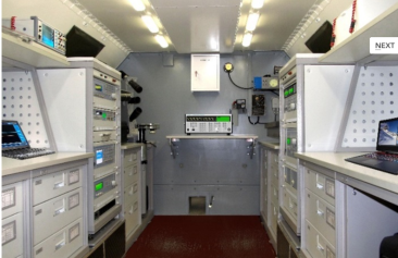
Mobile laboratory of measuring equipment PLIT-A2-4/1M
The complex is equipped with air conditioning, heating and ventilation systems to create and maintain a preset temperature level (20 ...25) ° C in the van body, at an outdoor temperature from minus 40 ° C to 40 ° C.
PLIT-A2-4/1M is equipped with a removable diesel electric unit with a capacity of 16 kW, which ensures the functioning of all systems in autonomous mode.
A set of functionally related working standards, special equipment and automation tools allows you to implement comprehensive metrological maintenance of measuring instruments at workplaces
TEKHNOYAKS
Moscow
Produced in: Moscow
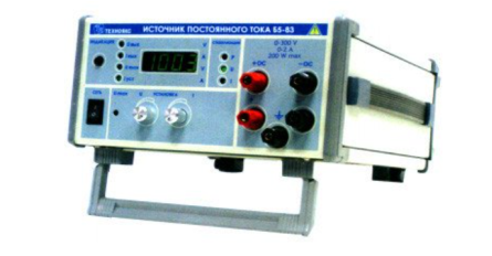
DC power supply B5-83
The B5-83 DC power supply is designed to provide constant
voltage and current to devices and equipment during the development, production,
operation and repair of electronic devices.
- Allows harsh operating conditions
- Wide range of currents and voltages at a maximum power of 200 watts
Technical specifications
Output voltage setting range from 3 to 300 V
Output current setting range from 0.05 to 2 A
Electrical output power, not more than 200 watts
The main error of the output voltage setting is ± 2 V
The main error of setting the output current is ± 0.02 A
Additional error in setting the output voltage caused by a deviation of the mains voltage from the nominal value by ± 10% ± (0.0001 · Uust + 3 mV)
Additional error in setting the output voltage caused by a change in the load current from 0.9 of the maximum value to zero ± (0.0002 · Uust + 10 mV)
Additional error in setting the output current caused by a deviation of the mains voltage from the nominal value by ± 10% ± (0.0002 · Iust + 1 mA)
Additional error in setting the output current caused by a change in the load voltage from 0.9 of the maximum value to zero ± (0.0005 · Iust + 2 mA)
The change in the output voltage in the voltage stabilization mode with a deviation of the ambient temperature in the operating temperature range by ± 10 ° C, not more than ± 250 mV
Change of the output current in the current stabilization mode with a deviation of the ambient temperature in the operating temperature range by ± 10 ° C, not more than ± 10 mA
Operating temperature range from minus 10 to 50 °C
AC power supply 220 V, 50 Hz
Power consumption, no more than 350 VA
Overall dimensions, mm 240x128x313
Weight, not more than 5.5 kg
TEKHNOYAKS
Moscow
Produced in: Moscow
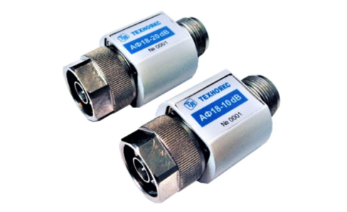
AF18-30dB
Basic properties
Wide frequency range;
Small VSWR values.
Operating conditions
Operating temperature range from minus 10 to 50 ° C;
The relative humidity of the air is up to 98% at a temperature of 25 ° C.
Technical specifications
Nominal attenuation, dB 30
Attenuation error, dB ± 1.5
VSWR 1.4
Frequency range, GHz 0-18
Input power, W 1
Type of coaxial connectors (according to GOST RV 51914-2002) IIIB-IIIP
TEKHNOYAKS
Moscow
Produced in: Moscow
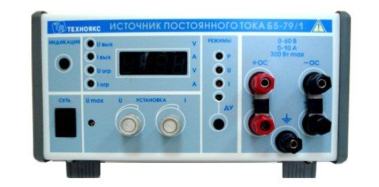
DC power supply B5-79/1
The source is capable of operating both independently and as part of automated measuring systems with interfaces such as RS-232 and ETHERNET
Technical specifications
Output voltage setting range from 0 to 60 V
Output current setting range from 0.2 to 10 A
Electrical output power, not less than 300 W
The main error of the output voltage setting is ± 100 mV
The main error of the output current setting is ± 100 mA
Additional error in setting the output voltage caused by a deviation of the mains voltage from the nominal value by ± 10% ± (0.0001 · Uust + 1 mV)
Additional error in setting the output voltage caused by a change in the load current from 0.9 of the maximum value to zero ± (0.0002 · Uust + 5 mV)
Additional error in setting the output current caused by a deviation of the mains voltage from the nominal value by ± 10% ± (0.0002 · Iust + 2 mA)
Additional error in setting the output current caused by a change in the load voltage from 0.9 of the maximum value to zero ± (0.0005 · Iust + 5 mA)
Instability of the output voltage for any 10 minutes during 8 hours of continuous operation, no more than ± 50 mV
Instability of the output current for any 10 minutes during 8 hours of continuous operation, no more than ± 50 mA
Operating temperature range from 10 to 50 °C
AC power supply 220 V, 50 Hz
Power consumption, no more than 500 VA
Overall dimensions, mm 240x128x313
Weight, not more than 6.0 kg
TEKHNOYAKS
Moscow
Produced in: Moscow

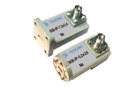
PKV-IP-7,2×3,4
Basic properties
Wide frequency range;
Small VSWR values.
Operating conditions
Operating temperature range from minus 10 to 50 ° C;
The relative humidity of the air is up to 98% at a temperature of 25 ° C.
Technical specifications
Waveguide cross section, mm 7.2×3.4
Type of coaxial connector (according to GOST RV 51914-2002) IP
Frequency range, GHz 25.96-37.50
VSWR 1.35
TEKHNOYAKS
Moscow
Produced in: Moscow
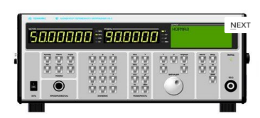
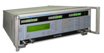
AC voltage calibrator H5-5
The calibrator is capable of operating both autonomously and as part of automated measuring systems with interfaces such as USB, RS-232, IEEE-488 (CPC).
Technical specifications
Ranges of reproduction of alternating electric voltage in the frequency range:
- from 10 Hz to 100 MHz from 3 MV to 3 V
- over 100 MHz to 2000 MHz from 30 MV to 3 V
Errors in the reproduction of alternating electric voltage in the frequency range:
- from 10 Hz to 100 kHz ± (0.066 – 0.8)%
- over 100 kHz to 100 MHz ± (0.85 – 2.5)%
- over 100 MHz to 700 MHz ± (1.5 – 12.7)%
- over 700 MHz to 2000 MHz ± (4.3 -14.0)%
General characteristics:
Operating temperature range from 5 to 40 °C
AC power supply 220 V, 50 Hz
Power consumption, no more than 180 VA
Overall dimensions, mm 495x217x411
Weight, not more than 24 kg
TEKHNOYAKS
Moscow
Produced in: Moscow