Catalog
Metrology
524 products
View:
- Selected: 0Areas of use
- Selected: 0Item names
- Selected: 0Manufacturer
- Selected: 0Made in
- Selected: 0Additional
View:
524 products
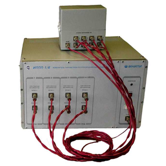
IPPP-1 Semiconductor Device Parameter Meters
Technical specifications:
4-channel automated system for measuring the parameters of semiconductors (including test structures on plates)
Study of the VAC of 2, 3, 4-pole
Parameters of each channel Source/meter:- U: ±2 V, ±30 V (200 mA),
±120 V (±10 mA), I: ±20, ±200 nA, ±2, ±20, ±200 Ma, ±2, ±10mA, (±120V), ±20,
±200 mA (±30V)
Source and meter error U, I ± 0.5%
Sensitivity of the U/I meter: 10 mv/ 0.1 pA
Graphs, tables, texts, databases
RS-232C interface, computer software
Dimensions, weight: 450x266x444 mm, 23 kg
Power supply: ~220V, 120 VA
MNIPI
Minsk
Produced in: Belarus, Minsk
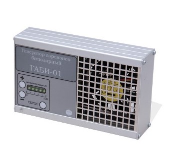
GABI-01 Aeroion generator bipolar
from
15 000 ₽
It is used to correct and create in the workplace the necessary concentrations of light aeroions of both negative and positive polarity in accordance with sanitary rules and regulations of the SanPiN 2.2.2/2.4.1340-03 . It is used for local antistatic treatment of charged surfaces during various technological processes.
NMT-ZASHCHITA
Moscow
Produced in: Moscow
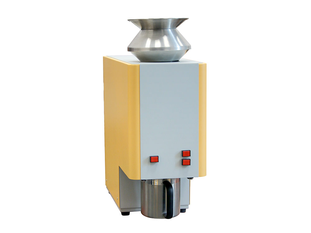
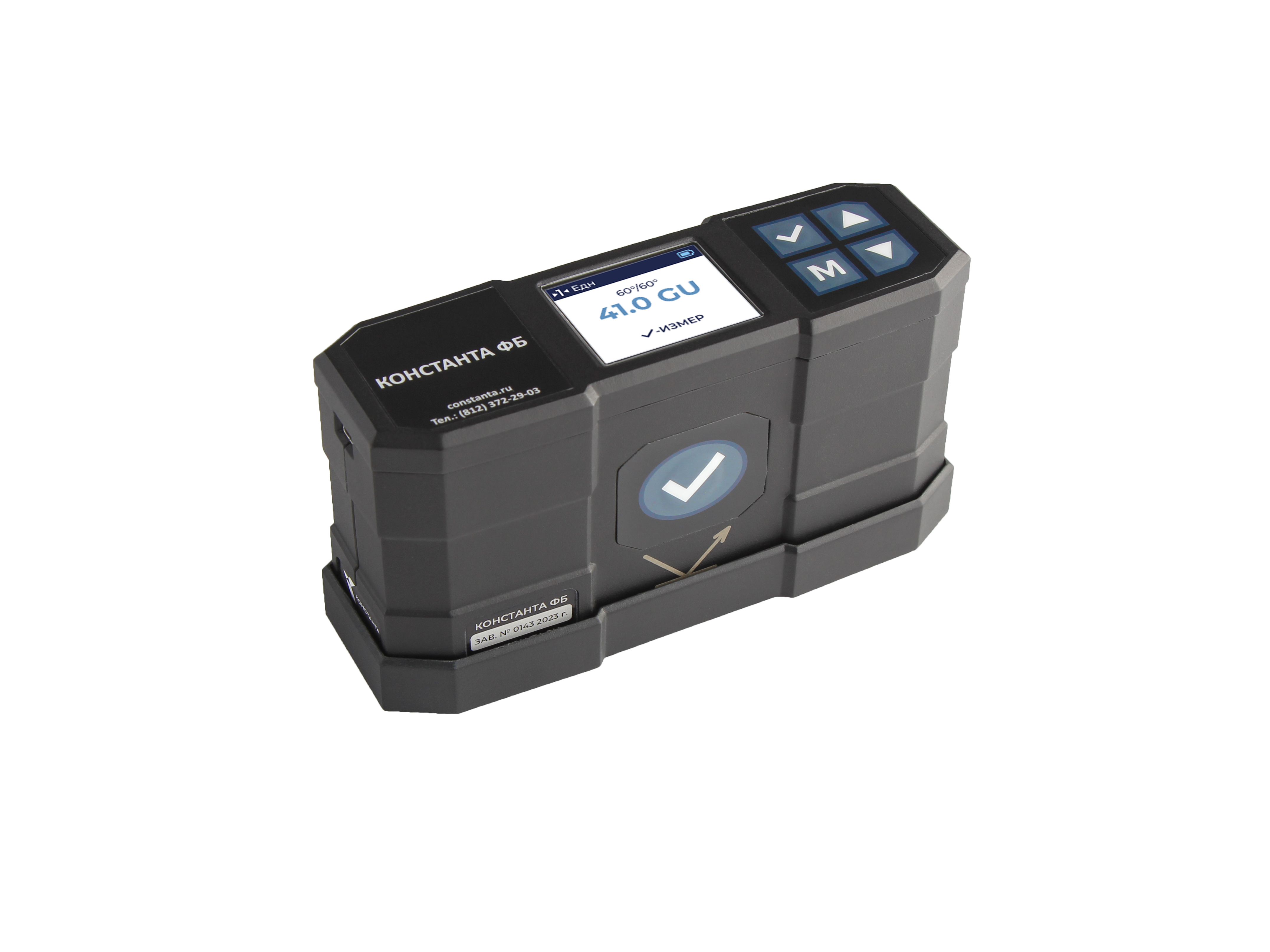
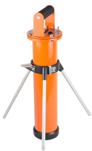
Purka liter MEASURE
1 supp.
The principle of operation is based on measurement by filling the container for the measured product with 1 liter of grain and measuring the mass of this grain. PECULIARITIES:
1. Drop weight design no assembly required
Thanks to a fundamentally new design of the purka, the determination of nature is carried out quickly. Significantly reduced analysis time. No special training of personnel is required to work on the MERA purka.
2. Stability and reproducibility of results. The stable and repeatable movement of the knives ensures the stability of the work of the purka and an accurate, stable, reproducible determination of the nature (± 1g at 10 measurements).
3. Quick and easy cleaning
The convenient design of the device permits to clean it quickly and easily. Excess grain is removed into an empty container for the measured product by pressing the "RESET" button. After discarding the remaining grain, the purka is ready for the next measurement. The fundamentally new design of the MERA purka body and the automation of the analysis process allow you to quickly and easily get the result.
WORK ALGORITHM:
1.Fill the hopper with grain.
2.Install the empty container for the measured product into the device.
3. Press the "START" button on the control panel.
4. Weigh a container filled with 1 liter of grain and calculate the result.
5. Reset the remaining grain by pressing the "RESET" button. METROLOGICAL CHARACTERISTICS:
Indication error, g, no more than ±4.0
Variation of six dimensions, g, no more than 2.1
SPECIFICATIONS:
Overall dimensions (L×W×H), mm, no more than 600×230×620
Weight, kg, no more than 48
Power consumption, V×A, no more than 100
Supply voltage with a frequency of 50±1 Hz, V 220 (+15...-20)%
GK EKAN
Saint Petersburg
Produced in: Saint Petersburg
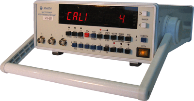
Frequency meters H3-88
Designed for measuring the frequency and period of sinusoidal and pulse signals, measuring pulse duration, time intervals, pulse duty cycle, frequency ratio of electrical signals, counting the number of pulses, output of reference frequency signals.
Technical specifications:
Input to (sinusoidal signal) - range 100 - 2500 MHz
Input A, C (sine, pulse) - range 0.01 - 200 MHz
Counting time: input A, C – 1, 10, 102, 103, 104 ms; login to – (16•1), (16•10), (16•102), (16•103), (16•104) ms
The number of averages. the period of the. vx. signal - 1, 10, 102, 103, 104
Timestamp period – 10-7, 10-6, 10-5, 10-4, 10-3
Borehole measurement at inputs A, C – 1.000001- 999999999
Frequency ratio in channels: A/S and C/A - 0.0001- 999999999; B/S - 0.5 – 999999999
Quartz thermostatic generator
The nominal frequency value is 5 MHz
Error: ± 5•10-8 - for 30 days, ± 10-7 - for 12 months
9 decimal places
Overall dimensions (HXHL) - 285x106x345 mm
Weight: 4 kg
Reference generator: 1x10⁻⁷ for 12 months.
Operating conditions: - 10° C ... +50° C
MNIPI
Minsk
Produced in: Belarus, Minsk
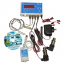
The complex for monitoring temperatures and other physical quantities with SMS notification
The complex for monitoring temperatures and other physical quantities allows you to receive timely and reliable information about the object at each level of production.
Currently the task of improving the production management process is becoming more and more urgent for industrial enterprises. It is especially important to solve this problem for those enterprises or their parts where the state of production parameters decisively affects the quality of products, and in some cases, the life and health of the consumer (for example, in the food industry or in the production of pharmacological preparations for their transportation). Taking into account the constant struggle for cost reduction, economic efficiency of production and competitiveness of products, it is necessary to ensure the correctness of management decisions and their adequacy to the current state of the process.
TEKHNO-AS
Kolomna
Produced in: Kolomna, Moscow region
MKS‑AT6101DR SPECTROMETER
- Measurement of pollution density and specific activity of radionuclides 134Cs and 137Cs in soils and soils;
- Measurement of the specific activity of radionuclides 137Cs, 134Cs, 131I in water, food, forestry products, agro-industrial complex and liquid radioactive waste;
- Determination of the content of natural radionuclides 40K, 226Ra, 232Th;
- Identification of radionuclides: 134Cs, 137Cs, 131I, 40K, 226Ra, 232Th;
- Measurement of the ambient dose equivalent of gamma radiation
Measurements without sampling with GPS-binding
Intelligent detection unit in an airtight container
Automatic determination of the thickness of the contaminated soil layer by radionuclides 137Cs and 134Cs
Atomtekh
Minsk
Produced in: Belarus, Minsk
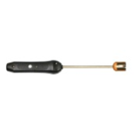
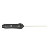
Surface smart probe L=150 mm SZPV.150P with built-in flash memory
from
13 524 ₽
Surface smart probe L=150 mm SZPV.The 150P with built-in flash memory is designed to measure the temperature of various materials by directly contacting the probe with the measuring object and transmitting the measured value via Bluetooth to devices with the ThermoMonitor based on the Android program.
Operating conditions of the SZPV.150P smart probe
Ambient temperature, °C: -20...+55.
Relative humidity, %: not more than 80 at T=35 °C.
Atmospheric pressure, kPa: 86...106.
Functionality of the SZPV.150P smart probe
Measurement of physical quantities with a resolution of 0.01.
Recording of measured values at intervals from 5 seconds to 23 hours 59 minutes 59 seconds (only smart probes with built-in memory).
Transmitting data about measured physical quantities via Bluetooth to a device with the ThermoMonitor based on the Android program.
Transmitting information about the state of charge of the built-in battery via Bluetooth to a device with the ThermoMonitor based on the Android program.
Automatic transition to sleep mode after 50 seconds.
The ability to connect an external power supply.
Calibration capability.
TEKHNO-AS
Kolomna
Produced in: Kolomna, Moscow region
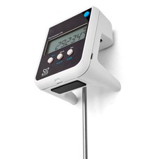
Laboratory electronic thermometer LTA-M
The error is ±0.2 °C in the range of -196...+300 °C.
The minimum immersion depth of the sensor is 75 mm
Overall dimensions of the electronic unit 80x75x100 mm
Weight 0.25 kg
Termeks
Tomsk
Produced in: Tomsk
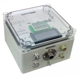
Multifunctional UKRV-2 air flowmeter
Purpose:
measurement of the volume of air pumped through the analytical filter;
measurement of volumetric air flow through an analytical filter.
Features:
output of information to the LCD indicator;
automatic and manual control of an external actuator (valve, crane);
obtaining information about the analytical filter used using a barcode reader;
transmission of data on the state of the device, the measured volume flow and the pumped volume of air to communication channels;
providing access to information via the RS-485 interface;
work both independently and as part of radiation monitoring systems
Doza
Zelenograd
Produced in: Moscow
Smart submersible probe L=300 mm SZPG.300P with built-in flash memory A
from
12 627 ₽
The smart submersible probe L=300 mm SZPG.300P with built-in flash memory is designed to measure the temperature of various materials by directly contacting the probe with the measuring object and transmitting the measured value via Bluetooth to devices with the ThermoMonitor, Android program installed.
Operating conditions of the SZPG.300P smart probe
Ambient temperature, °C: -20...+55.
Relative humidity, %: not more than 80 at T=35 °C.
Atmospheric pressure, kPa: 86...106.
Functionality of the SZPG.300P smart probe
Measurement of physical quantities with a resolution of 0.01.
Recording of measured values at intervals from 5 seconds to 23 hours 59 minutes 59 seconds (only smart probes with built-in memory).
Transmitting data about measured physical quantities via Bluetooth to a device with the ThermoMonitor, Android program installed.
Transmitting information about the state of charge of the built-in battery via Bluetooth to a device with the ThermoMonitor, Android program installed.
Automatic transition to sleep mode after 50 seconds.
The ability to connect external power.
Possibility of calibration.
TEKHNO-AS
Kolomna
Produced in: Kolomna, Moscow region

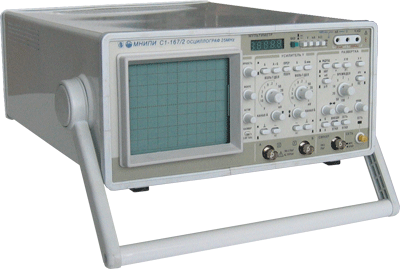
Digital oscilloscope C8-43
It is designed to study periodic signals in the frequency band 0-50 MHz and single electrical signals by registering them in digital memory with a sampling frequency of up to 50 MHz, observing their shape on a liquid crystal display (LCD), measuring the amplitude and time parameters of the signal under study.
Description:
2 mV...10 V/div; 10 ns...100 s/del
ADC: 2 channels, 100 MHz, 8 bits, 64 KB/channel
Equivalent sampling rate of 10 GHz
Marker measurements U: ±2.5%,T: ±1.5%
Pre-start, averaging,filtering
Familiar management interface
High-quality, "live" image
Additional modes in the "MENU"
Low price
Screen 80x100 mm (CRT made in Holland)
Dimensions, weight: 120x300x380 mm, 7 kg
Power supply: ~220V, 80 VA
MNIPI
Minsk
Produced in: Belarus, Minsk