Catalog
Metrology
524 products
View:
- Selected: 0Areas of use
- Selected: 0Item names
- Selected: 0Manufacturer
- Selected: 0Made in
- Selected: 0Additional
View:
524 products
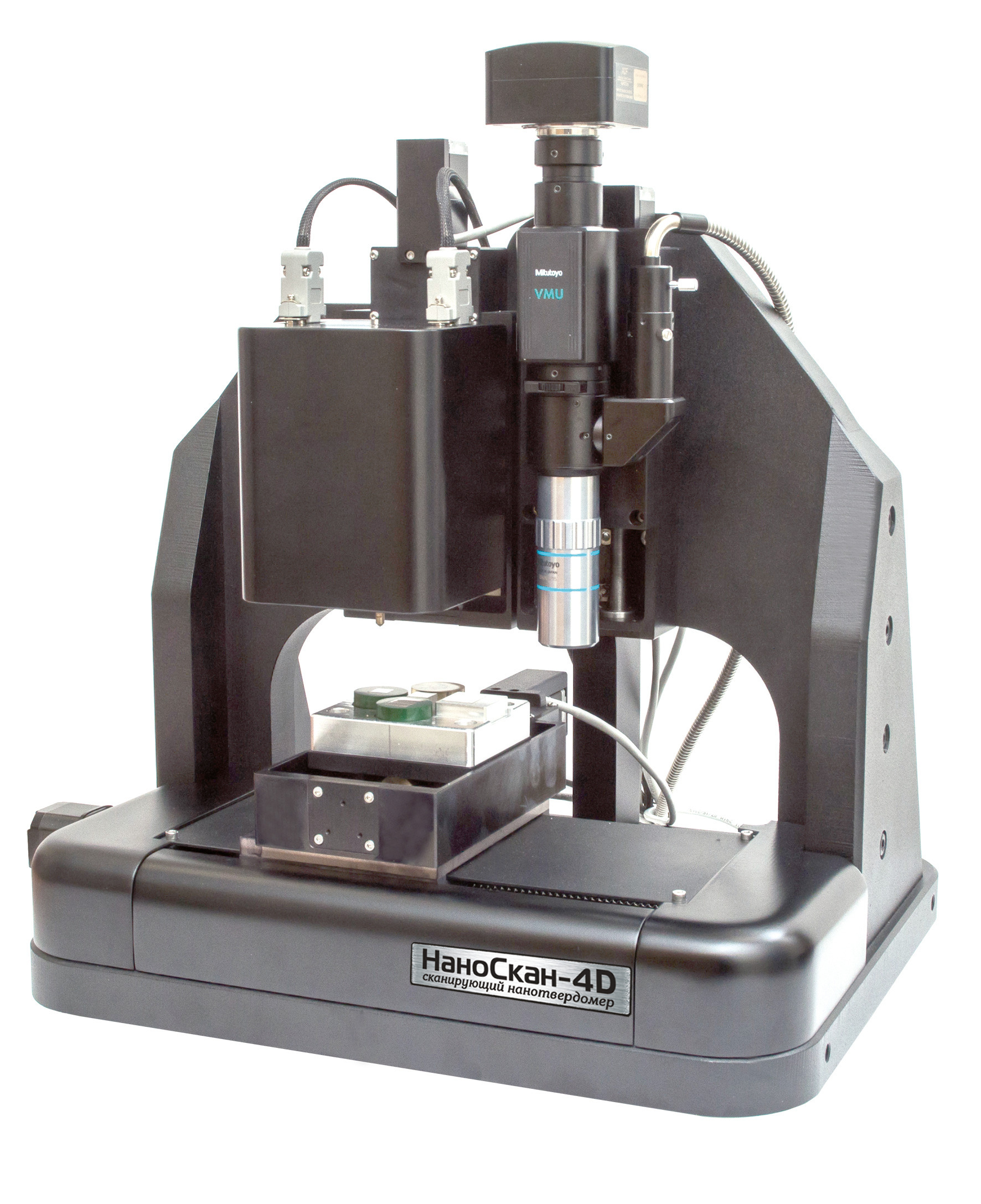
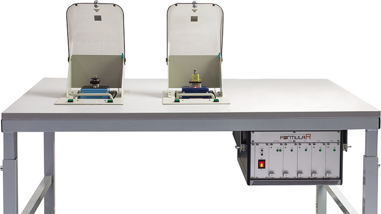
“NanoScan-4D Standard” nanosolidimeter by Nanoscan
The basic model of a nanohardness tester that implements the main methods for measuring hardness, Young's modulus, and a number of other mechanical parameters. The nanohardness tester implements the methods of static indentation, dynamic indentation and scratching. It is possible to measure the surface relief in the contact or semi-contact profilometer mode. The presence of an optical microscope ensures high accuracy of the mutual positioning of the indenter and the object of study. Additional components and sensors are available for this model.
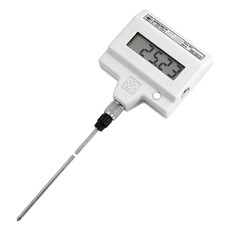
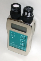
Laboratory electronic thermometer LT-300-N
The measurement range is -50...+300 °C.
Up to +200 °C resolution 0.01 °C, error ±0.05 °C (Class C according to ASTM E2877).
The minimum immersion depth of the sensor is 75 mm
Overall dimensions of the electronic unit 75x80x35 mm
Weight 0.2 kg
Termeks
Tomsk
Produced in: Tomsk

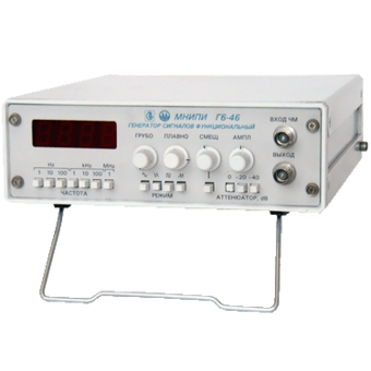
Generator G6-46
Technical specifications:
Frequency range, from 0.1 Hz to 1 Frequency range, from 0.1 Hz to 1 MHz Frequency setting error, ± 1 % Signal amplitude:
- at a load of 600 ohms
- without load, not less than 5 V (10 V span) not less than 10 V (20 V span)Smooth signal attenuation, at least 20 dB Frequency stability in 15 minutes, no more than 0.5% Hz
Frequency setting error, ± 1 %
Signal amplitude:
- at a load of 600 ohms
- without load, not less than 5 V (10 V span) not less than 10 V (20 V span)
Smooth signal attenuation, at least 20 dB
Frequency instability in 15 minutes, no more than 0.5 %
MNIPI
Minsk
Produced in: Belarus, Minsk
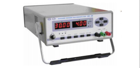
DC power supply B5-80 (81, 82)
The devices are used both independently and as part of automated
systems when working with control from a PC via the RS 232; RS 485 interface.
Technical specifications
Operating temperature range from 5 to 40 °C
AC power supply 220 V, 50 Hz
Power consumption, no more than 400 VA
Overall dimensions, mm 266x105x398
Weight, not more than 8 kg
TEKHNOYAKS
Moscow
Produced in: Moscow