Catalog

RII MNPO SPEKTR
25 products
View:
Telephone number:
E-mail:
mail@niiin.ru
Website: http://www.niiin.ru
Address:
Russia, Moscow, 35 building.1
Website: http://www.niiin.ru
Address:
Russia, Moscow, 35 building.1
- Selected: 0Areas of use
- Selected: 0Item names
- Selected: 0Manufacturer
- Selected: 0Made in
- Selected: 0Additional
View:
23 products
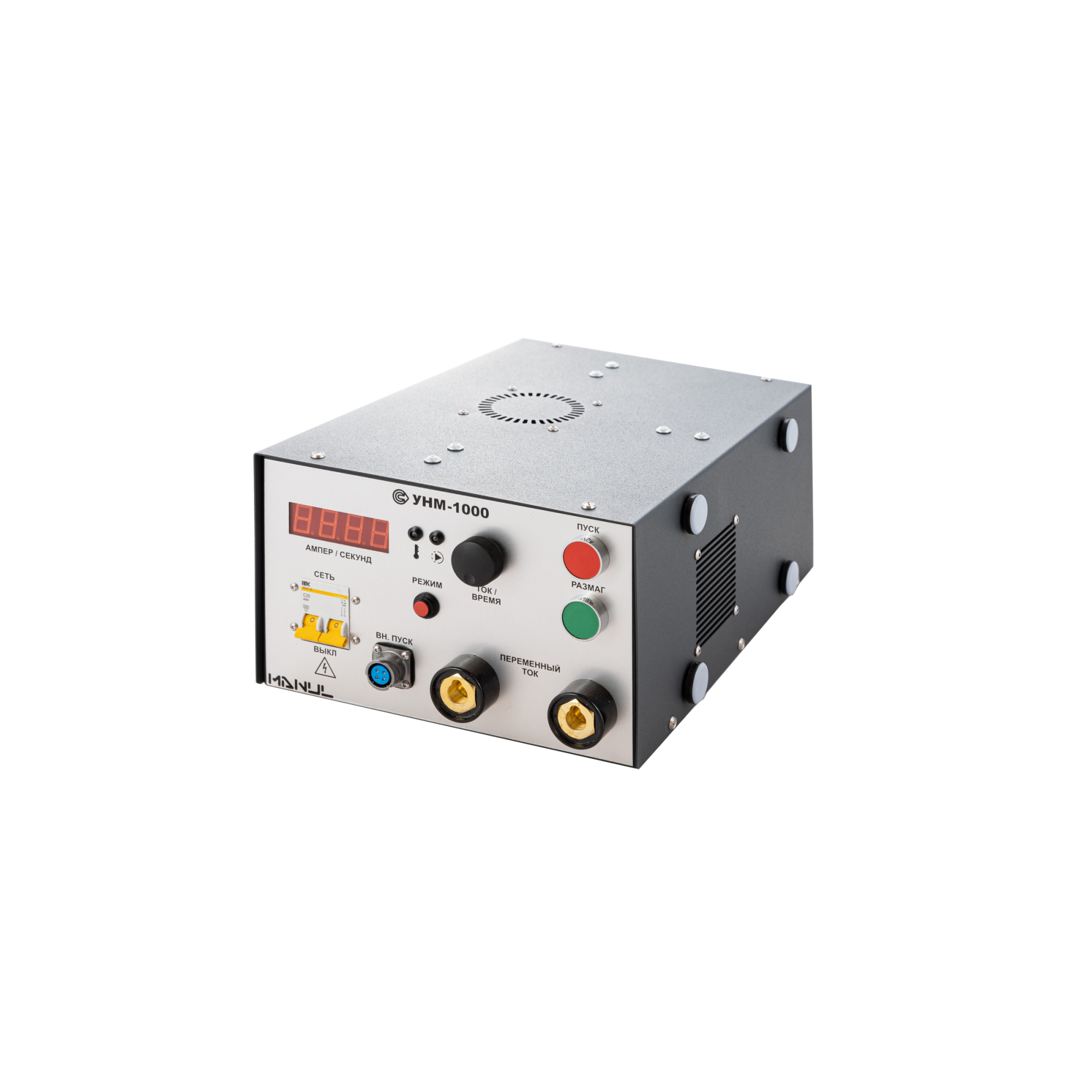
UNM-1000 portable magnetizing device, power unit
from
552 000 ₽
The UNM-1000 allows to detect internal, subsurface and surface defects of different types (cracks, flokens, delaminations, defects of welding seams, etc.) in parts, structural elements, units and mechanisms of industrial units, railway, auto, air vehicles, as well as petrochemical, gas and technological equipment during the manufacturing and repair stages or during routine inspections of the products being in operation.
The principle of operation of the UNM-1000 AC flaw detector
The magnetic powder method of detecting defects in products made of ferromagnetic materials is based on the ability of magnetic powder particles to settle in the defect zone, where inhomogeneities of the magnetic field created by the magnetizing device arise. Unlike devices based on permanent magnets, magnetic particle flaw detectors allow you to set the current and time of magnetization and automatically demagnetize controlled samples.
The UNM-1000 AC flaw detectors allow monitoring of products by the applied field method using various magnetization techniques. To do this, the alternating electric current generated by the flaw detector can be passed through a magnetizing cable or directly through a controlled product connected to the flaw detector using electrical contacts. The value of the current used for magnetization and demagnetization of the product is set by the operator of the device.
Design features and advantages
The UNM-1000 flaw detector is a portable device, which allows you to control the quality of products made of ferromagnetic materials both in production and in laboratory conditions. The basic set of equipment for magnetic particle flaw detection includes a UNM-1000 magnetizing device, a power cable for power supply from a single-phase AC network with a voltage of 220 V, and technical documentation. At the request of the customer, electrical contacts and a magnetizing AC cable can be additionally supplied.
The advantages of the UNM-1000 device of the MANUL series include:
the possibility of monitoring both in the applied magnetic field with longitudinal magnetization using power cables, and with circular magnetization by passing current through the controlled product;
wide range of magnetization current adjustment from 50 to 1000 A;
automatic demagnetization of controlled products;
high performance;
the device is compact and has light weight;
the degree of protection from external influences is at least IP40.
Scope of application of magnetic particle control means
Due to its versatility, simplicity and ease of operation, the UNM-1000 magnetic particle flaw detector can be used in almost all non-destructive testing laboratories of workshops and assembly shops of the automotive and aviation industries, railway transport, for the needs of civil and military shipbuilding. Also, the UNM-1000 magnetic powder control device can be successfully used in the energy sector, in the production of pipelines, metal structures, construction equipment and related industries. Technical characteristics of the portable magnetizing device UNM-1000 fully complies with the requirements of the following standards: GOST R 56512-2015, GOST R 53700-2009 (ISO 9934-3:2002), GOST R 50.05.06-2018, GOST R ISO 10893-5-2016, GOST ISO 17638-2018, RD 34.17.102-88, RD-13-05-2006 , as well as other national and foreign regulations documents on standardization of magnetizing devices and flaw detectors for magnetic powder control.
Technical specifications
• Magnetization current: up to 1000A (RMS), 4.3V,50 Hz
• Demagnetization mode
• Weight: no more than 20kg
• Overall dimensions (W×H×D): 290×160×450 mm
• The device is powered by 220V, 50 Hz
RII MNPO SPEKTR
Moscow
Produced in: Moscow
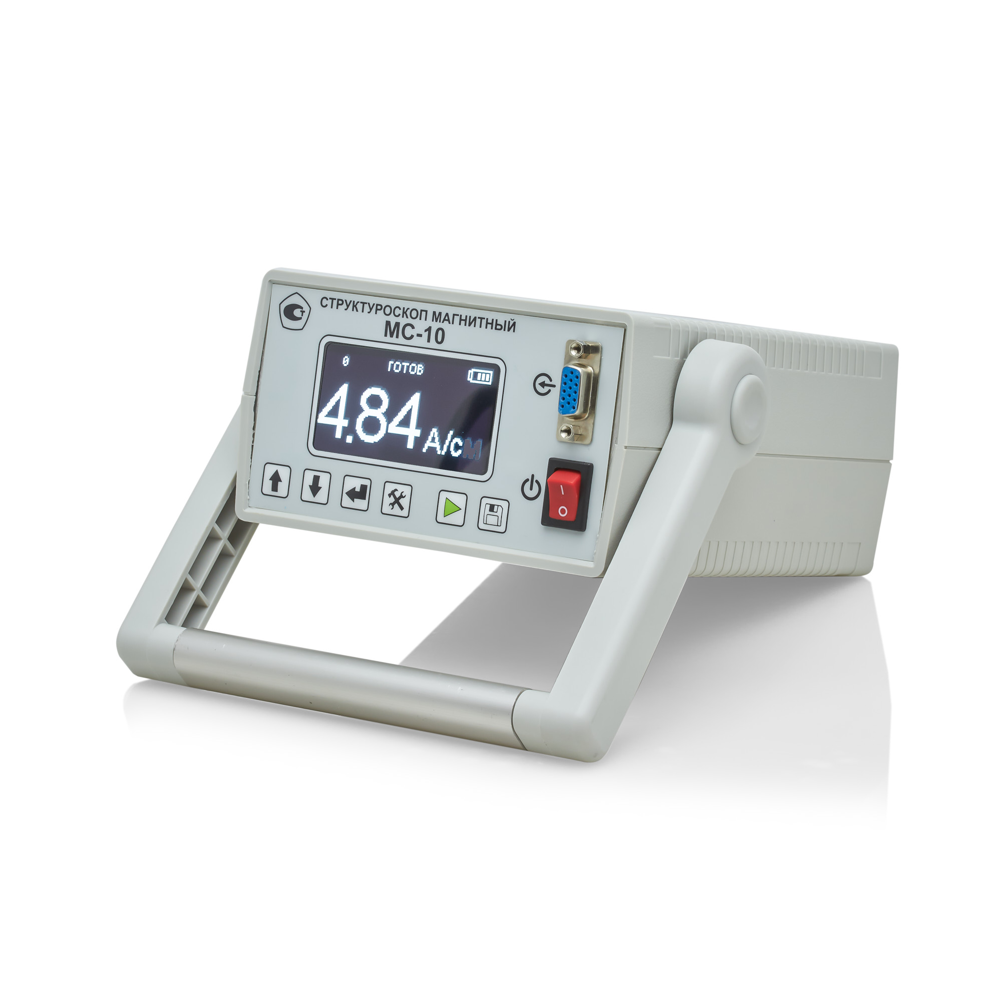
MS-10 Magnetic Structuroscope
from
310 500 ₽
Distinctive features:
- Non-destructive testing of strength, plasticity and viscosity of parts and structures made of ferromagnetic steels and cast iron according to the following standards: GOST 30415-96, OST 14-1-184-65, TU-14-1016-74
- Non-destructive testing of the depth and hardness of surface-hardened layers on steel and cast iron parts;
- Quality control of low-temperature tempering of cutting and measuring tools, bearing steels;
- Control of uniaxial elastic stresses;
- Control of the uniformity of the properties of massive parts.
Technical specifications:
The range of coercive force of the material of the controlled products, A/cm, is 1.0...60.
The limit of the permissible basic absolute error of measurements of the coercive force (Ns) on standard samples at a normal ambient temperature of 20 ± 5°C does not exceed the values of 0.1+0.04 Ns
(Ns stands for the measured value of the coercive force of the standard sample).
This error probability is provided with a gap between the converter and the surface of the controlled product not exceeding 0.5 mm.
Basic version: The structroscope is powered by a battery.
Extended version: It is possible to work on 220V/50Hz grid.
The time of setting the operating mode after power on, min: no more than 2
Time of one measurement, sec: no more than 6
Continuous operation time (without recharging), h: at least 16
Internal memory: up to 512 series of 512 measurements each with the possibility to view the results
Operating temperature range: -20°C to +40°C;
Overall dimensions, (length x width x thickness), mm:
electronic unit: 190x140x80
converter: 135x75x100
Weight, kg:
the electronic unit with a battery: 2.3 ± 0.05
the converter: 1.3± 0.05
Basic version kit:
Ia5.173.023 Electronic unit: 1 pc.
Ia5.125.061 Converter: 1 pc.
Ia8.896.121 Control sample of coercive force (plate PN-1): 1 pc.
Ia8.896.122 Control sample of coercive force (plate PN-2): 1 pc.
Bag-case: 1 pc.
Charger: 1 pc.
Ia2.778.042 RE Operating Manual: 1 copy.
Ia2.778.042 FO Form: 1 copy.
Ia2.778.042 MP Verification instructions: 1 copy.
Extended version:
Additionally, it can be equipped with a Bluetooth® module for communication with a PC and software for receiving and processing data.
It can also be equipped with a small-sized converter.
RII MNPO SPEKTR
Moscow
Produced in: Moscow
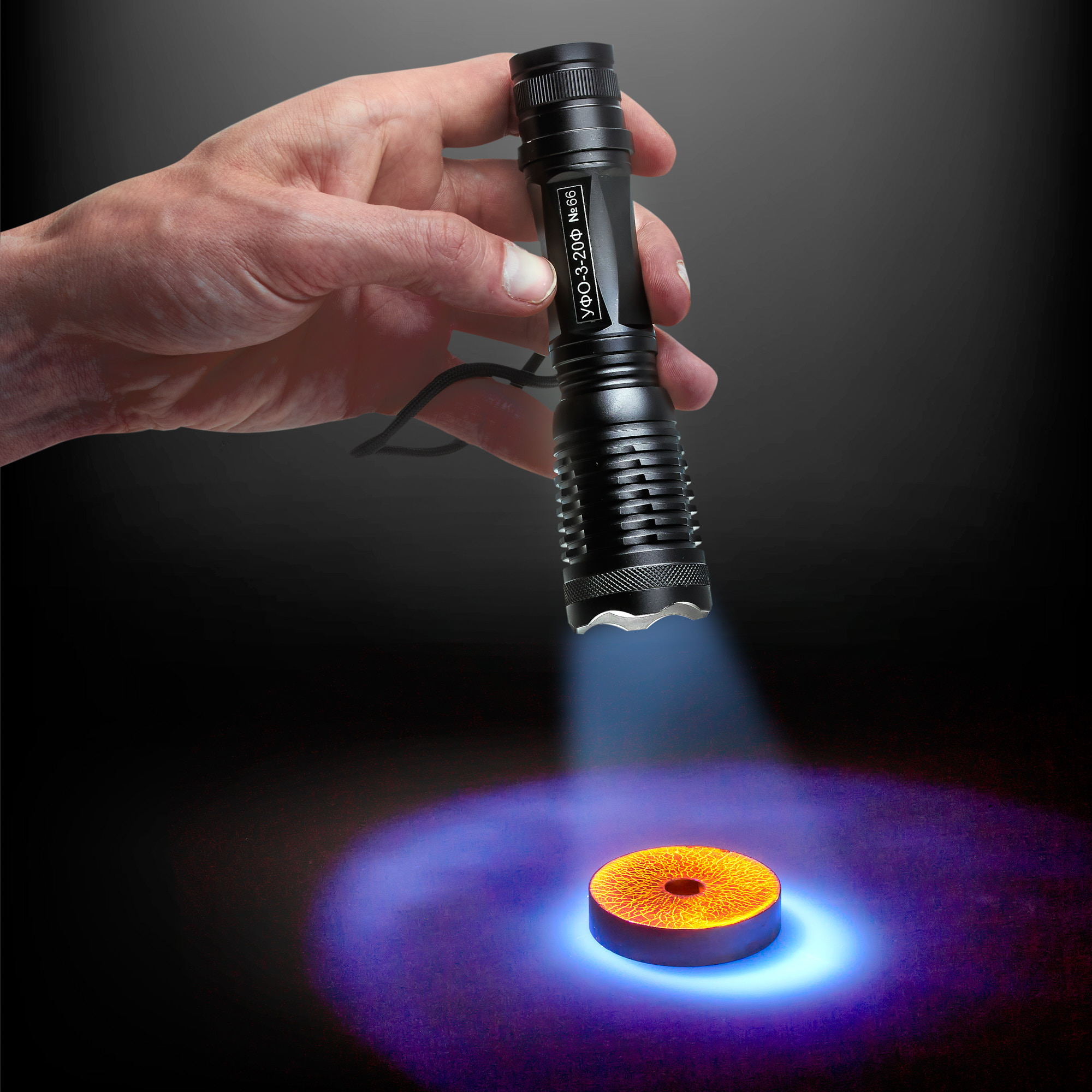
UFO-3-20F UV Irradiator
from
54 000 ₽
The principle of operation of the device
The principle of operation of the irradiator is based on the conversion of DC electrical energy into a normalized flow of ultraviolet radiation in the optical wavelength range of 350 ... 400 nm with a maximum at a wavelength of 365 nm.
Design features and advantages
The irradiator is a lantern consisting of an ultraviolet diode placed behind the focusing system, connected to a DC voltage converter, which supports the optimal mode of starting and functioning of the LED. Structurally, the irradiator is made in a lightweight duralumin housing, in the front of which there is a focusing system with an ultraviolet LED. The housing is equipped with a carrying strap. There is also a power on/off button on the case. As the power source of the irradiator, a lithium-ion battery of type 18650 with a nominal voltage of 3.7 V or 3 AA batteries with a voltage of 1.5V. are used. An ultraviolet LED is used as a source of ultraviolet (UV) radiation.
The use of an LED distinguishes the UFO-3-20F irradiator from similar devices using UV lamps, it provides:
high reliability and durability;
variable diameter of the UV radiation zone;
low current consumption and long continuous operation time;
instant readiness for the first and subsequent turn-on;
low weight, compact;
high radiation intensity;
stability of the characteristics of the irradiator, both during operation and throughout its entire life;
wide operating temperature range.
Scope of application
The UV-3-20F irradiator (lantern) is used for ultraviolet irradiation of the surface of various parts, assemblies and mechanisms during flaw detection by fluorescent methods of non-destructive testing at machine-building enterprises, chemical and petrochemical industries, railway, automobile, water and aviation transport, during the laying and operation of pipelines, in construction, agriculture. The device can be used to check the quality of welds and internal surfaces of closed tanks. The luminescent method makes it possible to ensure high brightness and contrast of the indicator pattern, and, consequently, high sensitivity, especially on parts and products with a dark surface.
Technical specifications
The range of radiated wavelengths, nm 350...400
Ultraviolet irradiation at a distance of 300 mm, W/m2, not less than 20000
with a diameter of the irradiated area of 100 mm not less than 2000
Power supply from a lithium-ion battery type 18650 voltage of 3.7 V,
or 3 AA batteries with a voltage of 1.5V
Continuous operation time without recharging the battery, h, at least 4
Maximum irradiance at the wavelength, 365 nm
Dimensions (diameter x length) 40 x 150
Weight (without batteries), kg, not more than 0.2
RII MNPO SPEKTR
Moscow
Produced in: Moscow
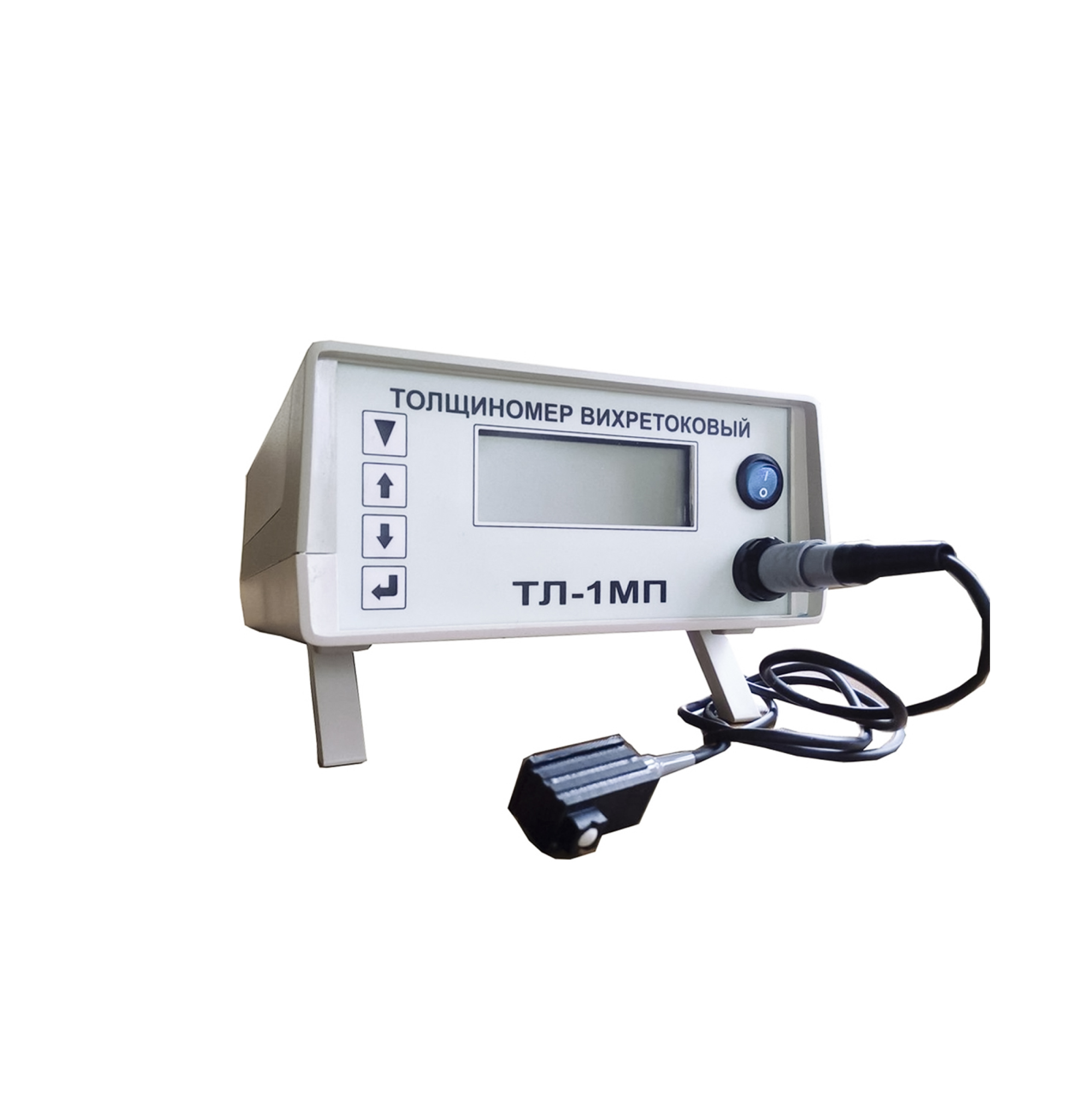
TL-1MP Eddy Current Thickness Gauge
from
1 110 000 ₽
The principle of operation of the electroplating thickness gauge:
A converter with an induction coil on a ferrite core generates a high-frequency signal (frequency 1 MHz), which is used to create an alternating magnetic field. As the converter approaches the conductive surface, an alternating magnetic field creates eddy currents, the magnitude of which depends on the characteristics of the metal base and the thickness of the coating. In turn, eddy currents create their own electromagnetic field, which can be received by an induction coil. The resulting signal enters the amplitude detector, after which it is transmitted to the processing unit, where it is digitized and displayed on the device readout. In addition to signal conversion, the processor is used to set the required gain, as well as the initial voltage offset, depending on the characteristics of the materials in the controlled object.
Features of the device design and advantages of the measurement method
The TL-1MP eddy current thickness gauge consists of an electronic unit with a display, a power supply and a converter. The device is controlled using four buttons located on the front panel of the electronic unit. The converter can be disconnected from the electronic unit during transportation or for convenience of storage. The advantages of the device include:
- convenience and ease of operation;
- small size and light weight, allowing the TL-1MP to be used in difficult conditions with limited access to the controlled area of the facility;
- high measurement accuracy;
- factory setting of the measuring instrument to the customer's requirements;
- high degree of localization of defects due to the small size of the converter.
Scope of application:
The service life of metal parts and components of mechanisms used in mechanical engineering is largely determined by their resistance to corrosion and surface wear. However, not all metals are sufficiently resistant to external destructive influences. Therefore, various electroplating coatings made of zinc, nickel, chromium, cadmium, tin, copper, silver and other metals are used to protect them. Even small fluctuations in the thickness of protective coatings can significantly affect the performance characteristics of parts, their service life, and interaction with other components. Therefore, measuring the thickness of the metal coating applied by the electrochemical method is important when conducting quality control of products. The use of the TL-1MP eddy current thickness gauge allows non-destructive quality control of electroplating coatings on the surface of metal parts in mass production conditions with special requirements for product quality. The device detects even small mechanical defects, the effects of abrasion, erosion, corrosion on the surface. Due to its ease of use, efficiency and reliability, eddy current thickness measurement is a standard method of quality control of products with electroplated coatings in such industries as mechanical engineering, aerospace industry.
RII MNPO SPEKTR
Moscow
Produced in: Moscow
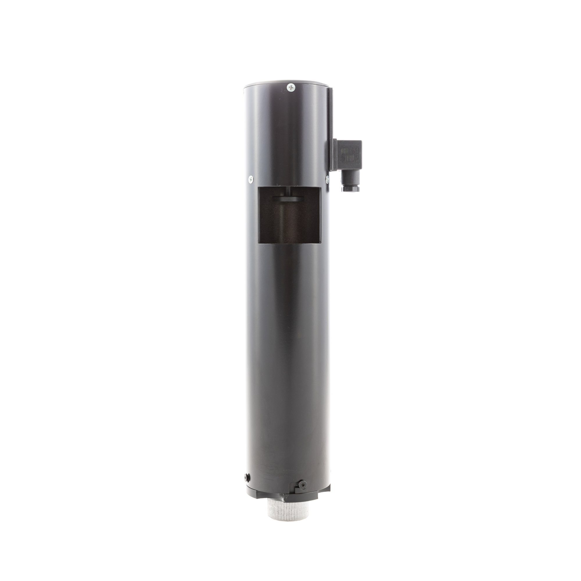
CD-1 Paint detector of defects 220V
from
60 000 ₽
The principle of operation:
The controlled extended product (pipe, rolled or wire) is passed through the working area of the flaw detector. When a defective area is detected, the flaw detector included in the automated system sends a signal to trigger the paint meter actuator, as a result of which the paint from the marker's aerosol can is applied to the surface of the controlled product through a window in the device housing.
Features and benefits:
- Any standard aerosol cans with a diameter of 68 mm can be used in the flaw detector;
- Easy replacement of the cylinder;
- The device does not require connection to the pneumatic line;
- High performance;
- The design of the CD-1 defect meter allows connection to any standard AC and DC electrical networks with rated voltages from 12 to 380 V.
Scope of application:
The CD-1 automatic paint sprayer is an auxiliary equipment and is used in conjunction with flaw detectors as part of in–line automated lines for marking defects in quality control of extended products made of various materials, ferrous and non-ferrous metals and alloys - welded, hot-rolled and cold-drawn pipes, rolled products, wire and products made of them.
The flaw detector can be used both in the production process and during input control on the consumer side at machine-building, transport, chemical and oil and gas enterprises.
*Custom-made versions for rated voltages can be of: 12, 24, 48, 110, 127, 220, 380V.
RII MNPO SPEKTR
Moscow
Produced in: Moscow
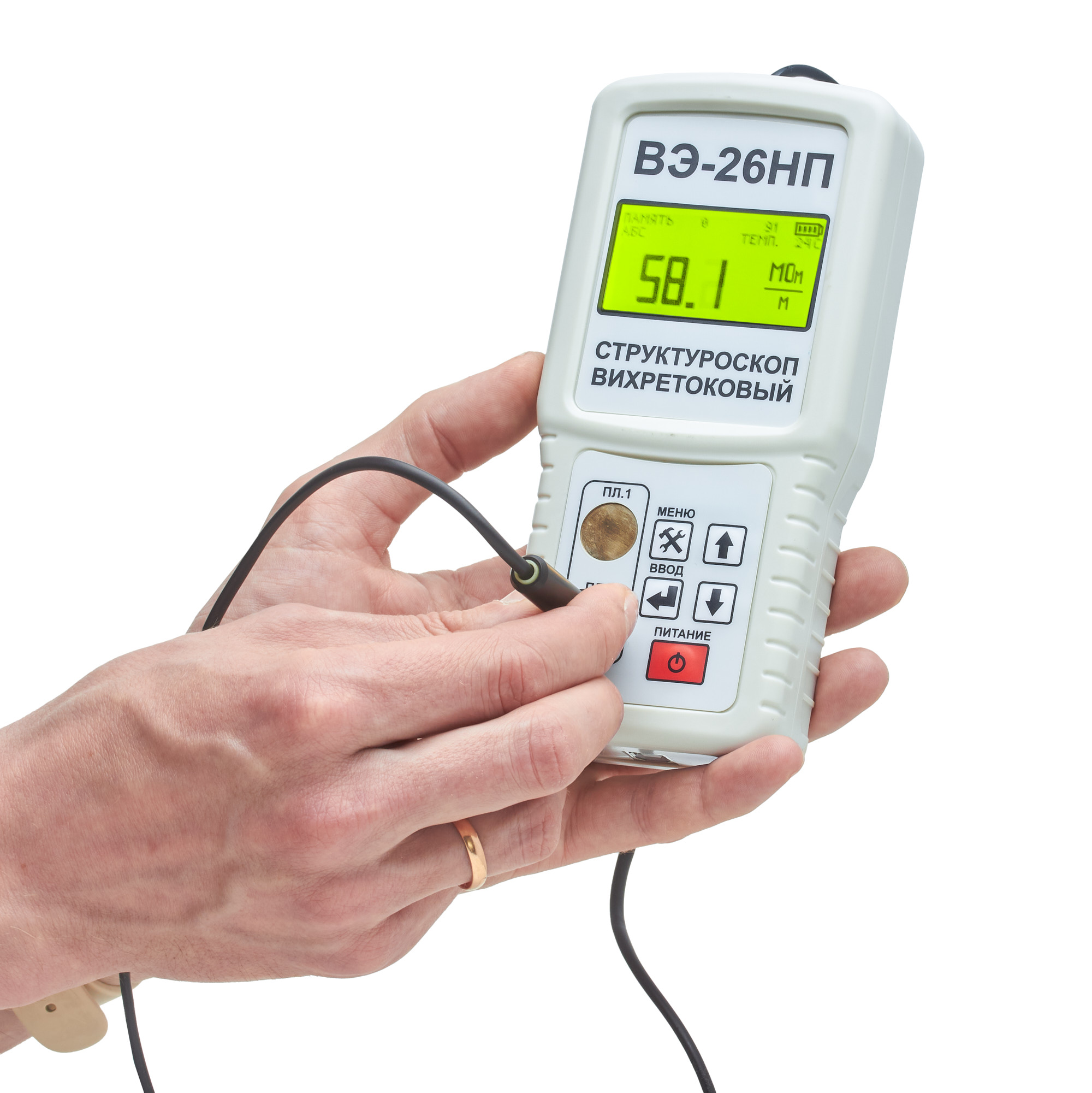
VE-26NP Eddy current structuroscope
from
195 000 ₽
Distinctive features:
The built-in thermometer allows you to take into account the influence of ambient temperature and improve the measurement accuracy. The built-in memory stores 4096 electrical conductivity measurement results for subsequent transfer to a PC.
Specifications:
Measuring range of the absolute value of specific electrical conductivity, MSm/m from 5 to 60
Measuring range of increments of electrical conductivity, MS/m from -9.99 to +9.99 Limit of permissible basic relative measurement error, % no more than 2 Permissible gap between the transducer and the surface of the controlled product, mm, no more than 0.25 Digital display of measurement results Power supply from RRZ type battery, V 9 Power consumption, mW, no more than 40 Operating temperature range, °C 5...40 Dimensions, mm 57*84*30 Weight, g 270±20
Measuring range of increments of electrical conductivity, MS/m from -9.99 to +9.99 Limit of permissible basic relative measurement error, % no more than 2 Permissible gap between the transducer and the surface of the controlled product, mm, no more than 0.25 Digital display of measurement results Power supply from RRZ type battery, V 9 Power consumption, mW, no more than 40 Operating temperature range, °C 5...40 Dimensions, mm 57*84*30 Weight, g 270±20
RII MNPO SPEKTR
Moscow
Produced in: Moscow
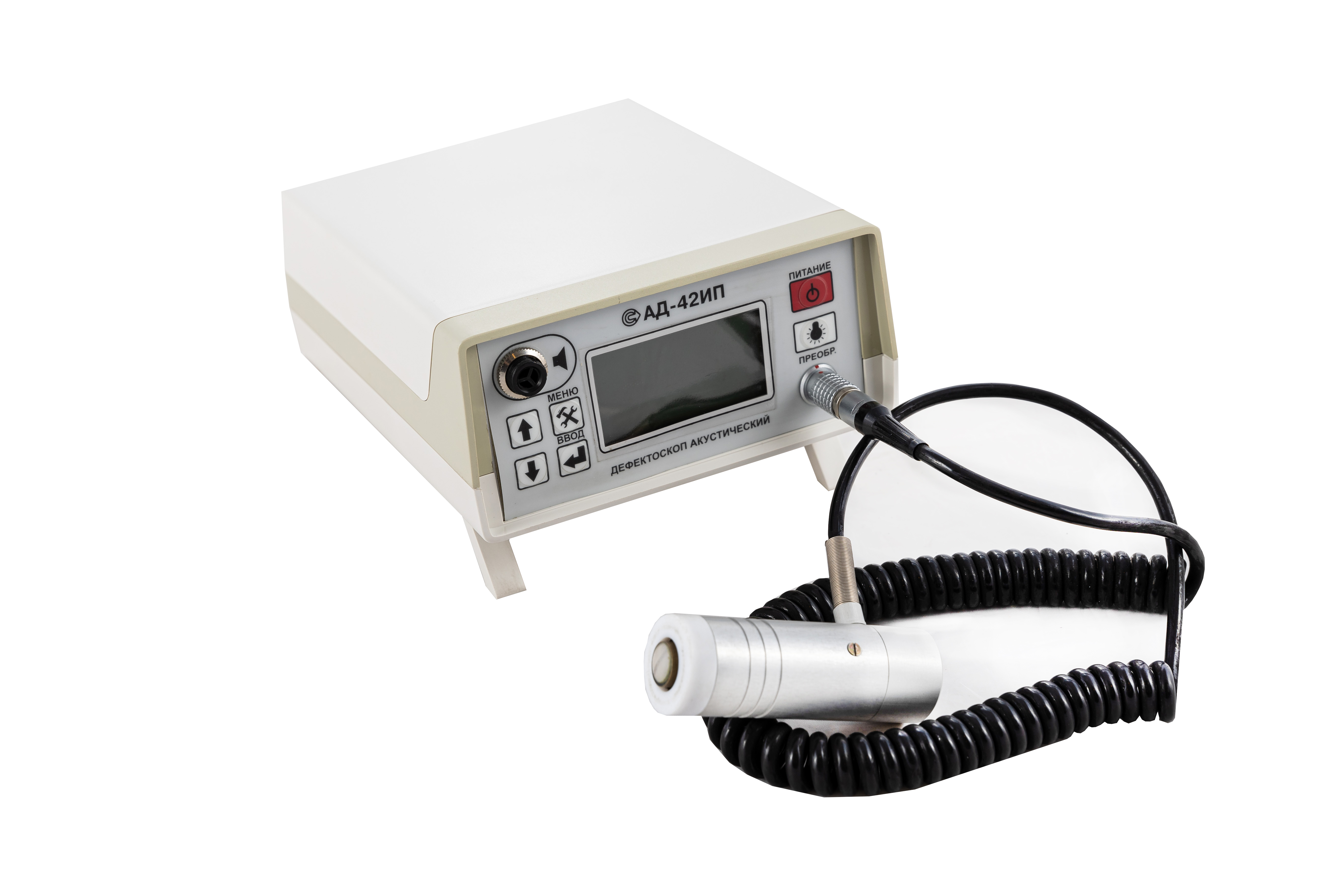
AD-42IP Acoustic Flaw Detector
from
442 500 ₽
It is especially effective for use in products made of composite materials (including with honeycomb filler).
Distinctive features:
The AD-42 IP is a compact acoustic system sensitive to changes in mechanical impedance caused by product defects. The indication of the device indicates that there are voids, non-adhesives, delaminations or changes in the structure of composite materials (including with honeycomb filler and laminated plastics) under the sensor.
The device is used to monitor various materials and their combinations.
The energy consumption of the unit is low because the converter is switched on when the sensor is placed on the monitored product.
Being light enough, the device allows you to perform monitoring in hard-to-reach places or in confined spaces.
The results of the control can be stored in the built-in non-volatile memory and transferred to a PC.
Converters
Options: - 3 types of converters for various tasks
Emitters: - 1 or 2 on each converter
Switching-on: - The converters are switched on when they are placed on a controlled object.
Technical characteristics:
Weight, kg: 0.73
Dimensions, mm: 210x150x70
Power supply: 4 AA batteries
Work without recharging the battery, h: 8
Battery discharge visual indication
The defect alarm is visual on the converter and audible on the instrument panel (or) in headphones.
RII MNPO SPEKTR
Moscow
Produced in: Moscow
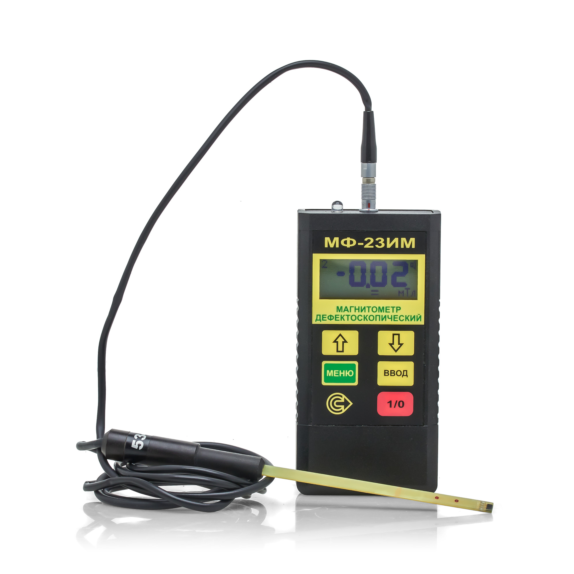
MF-23IM Flaw detection magnetometer
from
193 200 ₽
The MF-23IM flaw detection magnetometer allows you to determine the compliance of the ratio of the tangential and normal components of the magnetic field strength during magnetic particle testing using both the applied field method (AFM) and the remanent magnetization method (RMM) in accordance with the requirements of current regulatory documentation.
The MF-23IM flaw detection magnetometer meets the requirements in the field of non-destructive testing for the main industries: nuclear, energy, oil and gas complex, general and special engineering, railway transport, aerospace industry, elevator and crane facilities.
The flaw detection magnetometer is included in the State Register of Measuring Instruments (GRSI) under No. 20106-00. The magnetometer (milliteslameter) is also included in the register of measuring instruments, testing equipment and measurement methods used at JSC Russian Railways. The flaw detection magnetometer MF-23IM from the manufacturer is used to measure the parameters of constant, variable (industrial frequency) and pulsed magnetic fields when testing ferromagnetic products using the magnetic particle method, as well as to control the level of industrial interference. Specifications.
Magnetic field induction (strength) measurement range: - constant and variable (amplitude and average values) 0.5…1000 mT (4…8000 A/cm) - pulsed (amplitude value) 2…1000 mT (18…8000 A/cm) Indication of measurement results digital or digital + graphic Indicator liquid crystal display Power supply from 1 PP3 battery Current consumption, mA, no more than 15 Memory capacity for storing results 4080 Communication with a computer via infrared channel Dimensions of the electronic unit, mm, no more than 120x60x25 Weight of the electronic unit with battery, g 150
The minimum dimensions of the Hall transducer for the MF-23IM magnetometer make it possible to measure the induction and magnetic field strength in grooves, grooves, corner transitions, i.e. in those areas of the controlled product that are stress concentrators and the most dangerous from the point of view of crack formation; · Measurement of pulsed magnetizing field with pulse duration from 0.5 ms; · Small measurement error (see technical specifications table) · Compact size and low power consumption;
· The magnetometer has 2 modes for displaying measurement results – digital and graphic). The MF-23IM magnetometer in graphical display mode allows you to detect a demagnetizing pulse by displaying its shape and amplitude on a graphic display, as a result of which changes can be made to the magnetization circuit in a timely manner. · The software of the MF-23IM magnetometer allows you to flexibly configure not only the response thresholds, but also the time base, which allows you to tune out false indications caused by reverse emissions of the magnetic field or electromagnetic interference from operating power equipment (magnetizing devices or magnetic particle flaw detectors).
· Determination of the effective magnetization region, within which the tangential component of the magnetic field strength is sufficient for magnetic particle testing, and the ratio of the normal and tangential components of the magnetic field strength is less than or equal to 3. · Checking the mode of magnetization/demagnetization of test objects for compliance with the methodology/technological instructions for magnetic particle testing for a given object.
BASIC SET: Electronic unit Converter 1 Converter 2 Caliber PP3 battery CD with program Case Flaw detection magnetometer MF-23IM. Passport
RII MNPO SPEKTR
Moscow
Produced in: Moscow
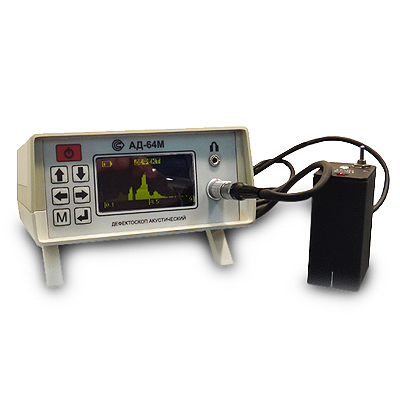
AD-64M Acoustic Impedance Flaw Detector
from
825 000 ₽
Control methods: Impedance method (IM) and free oscillation method (MSC)
Distinctive features:
- A wide range of controlled materials: from steel to foam and structures with soft external and internal elements
- Application of two complementary control methods
- One-way access
- Dry contact of the transducers with the controlled object
- Visual representation of information
- The ability to memorize and reproduce the setting modes, which excludes the use of control samples at the workplace
Technical specifications:
The minimum area of the detected defect, cm2: 1
The depth of detected defects in fiberglass, mm: up to 12...15
Light and sound signaling of defects
Number of measurements per second: 15
Weight, kg: 1
Self-powered by batteries
Continuous battery life, h: 8
Operating temperature range, °C: -10...40
RII MNPO SPEKTR
Moscow
Produced in: Moscow
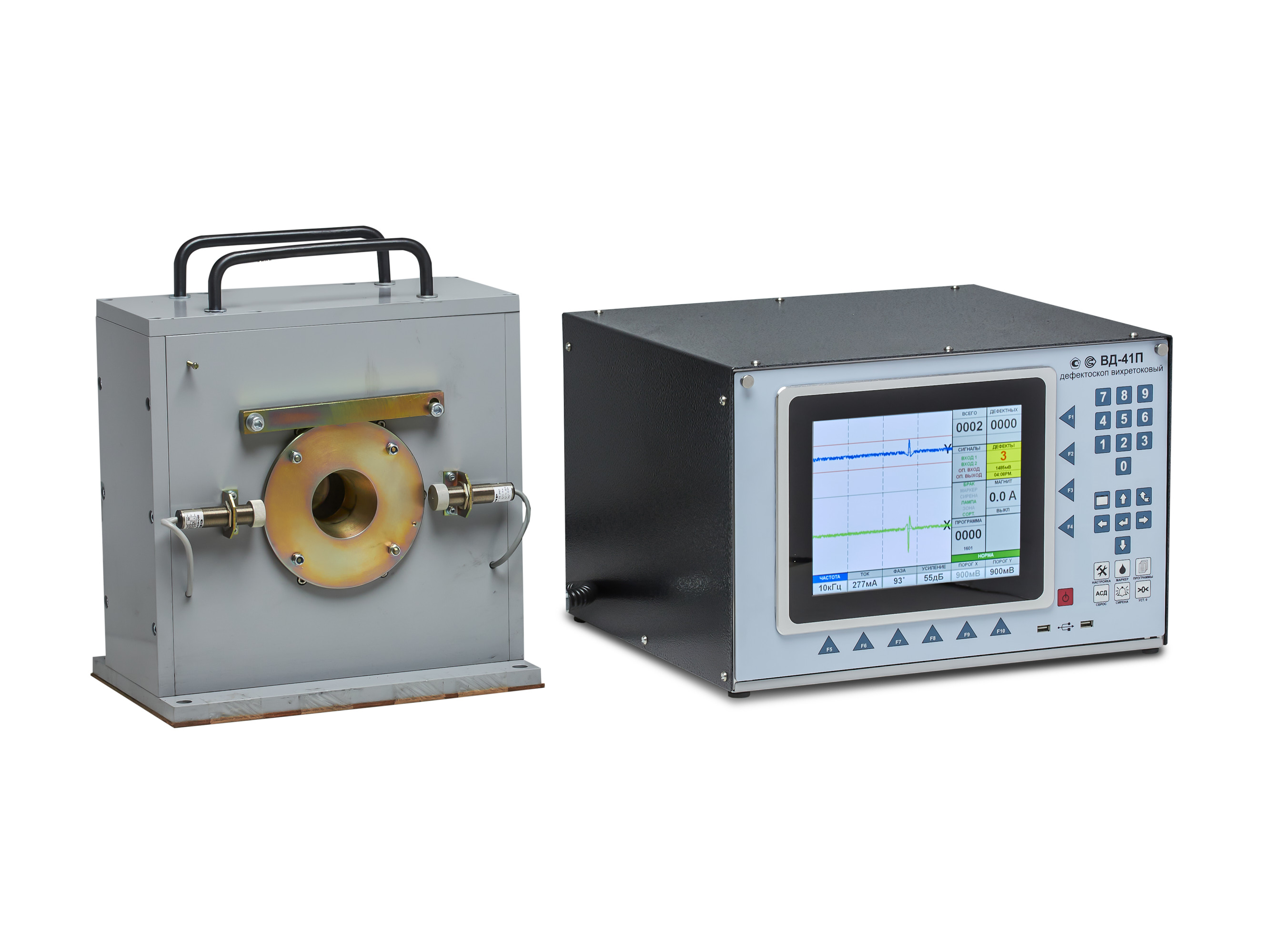
VD-41P Eddy Current Flaw Detector
Scope of application
The VD-41P eddy current flaw detector is designed to work as part of automated quality control lines at pipe-rolling and metal-rolling enterprises with continuous output control of products together with other auxiliary devices: a paint meter, a path sensor, an object presence sensor, an automatic sorter, a demagnetizer.
The device can also be used for input control at machine-building enterprises of the automotive, aviation, oil and gas, and agricultural industries.
Technical specifications:
Control frequencies: 1.0 – 100 kHz.
Control speed (line speed): 0.5 - 5 m/s.
The high-frequency filter is automatically adjustable depending on the speed.
Signal phase adjustment: 0 - 359° .
Converter current adjustment: 50 – 500mA.
Automatic monitoring of the operability of the measuring converter.
Data processing:
- Software adjustable filter.
- Signal evaluation using signal masks:
- circular mask,
- sector masks.
- Sorting by control results.
Display: 10.2” (26 cm) touch LCD (800x600).
Operating system used: WINDOWS® 7.
Dialog language: Russian, other languages (optional).
Applicable eddy current converters: overhead type, through type, sector type.
Interfaces:
- Connector for the converter unit.
- External automation control connector.
- 4 outputs with delay adjustment - "dry contact".
- 2 external information inputs.
- VGA interface for connecting an external monitor.
- USB 2.0.
- Network: Ethernet (TCP/IP).
- Other interfaces on special order.
Power supply: 220 V, 50 Hz.
Operating temperature range: 0 to +40°C.
Type of climatic performance - UHL 4 (i.e. for moderate and cold climate).
Enclosure protection degree: IP 53.
Dimensions, w/h/d: 471 x 285 x 460 mm / can be built in a 19” rack/cabinet.
Weight: approx. 20 kg.
RII MNPO SPEKTR
Moscow
Produced in: Moscow
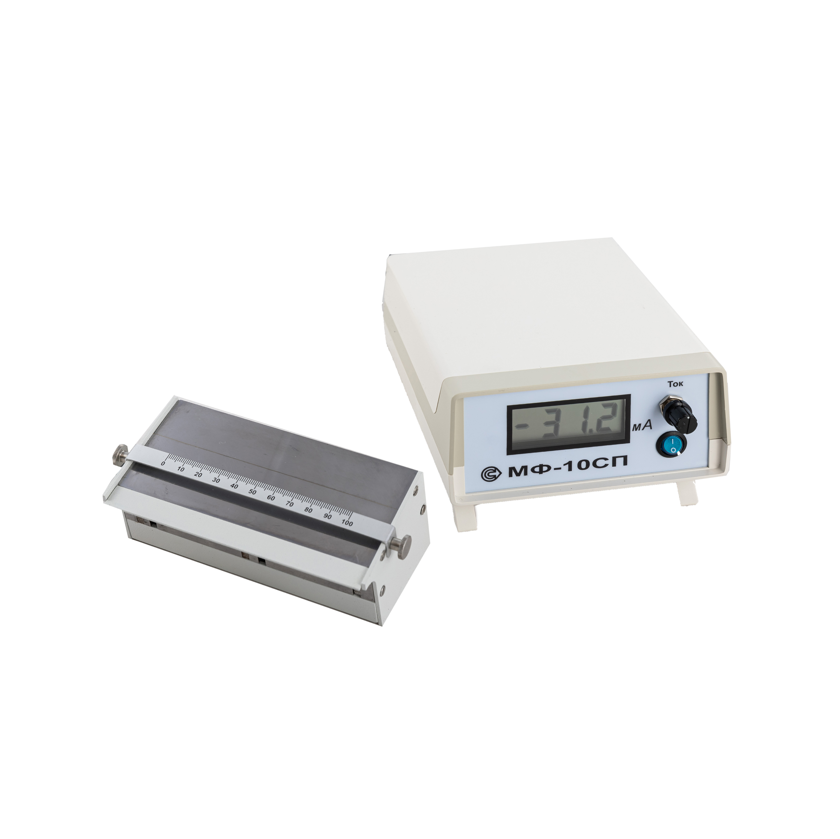
MF-10SP Device for checking the quality of magnetic powders and suspensions
from
225 600 ₽
Technical specifications:
The range of regulation of the magnetizing current is 0.06 to 0.10 A.
The magnetizing current indication is digital.
The nature of the change in the magnetic field is uniformly decreasing along a scale with a length from 0 to 100 mm.
The width of the opening of artificial discontinuities in the magnetic circuit of the electromagnet is 50 and 100 microns
The electrical power supply of the device is carried out from an alternating current network with a frequency of 50 Hz, a voltage of 220 V.
Power consumption is no more than 20 VA.
Overall dimensions:
- electronic block, mm, no more: 230x150x70
- electromagnet, mm, no more: 155x65x70
Weight:
- electronic unit, kg, not more than: 1
- electromagnet, kg, not more than: 1.6
Equipment of the MF-10SP:
- electronic unit - 1 pc.
- electromagnet - 1 pc.
- suspension collection tray - 1 pc.
- VP-1-1-0,25 A protector - 2 pcs.
- carrying case - 1 pc.
- passport, operating manual, calibration instruction - 1 set.
RII MNPO SPEKTR
Moscow
Produced in: Moscow
