Catalog
Equipment
2226 products
View:
- Selected: 0Areas of use
- Selected: 0Item names
- Selected: 0Manufacturer
- Selected: 0Made in
- Selected: 0Additional
View:
2226 products
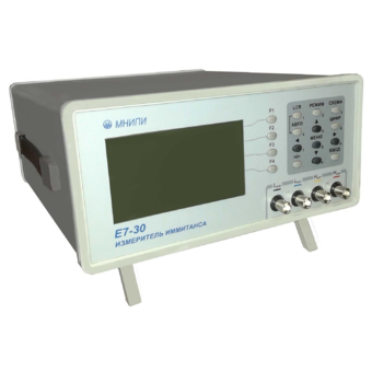
Immitance meter E7-30
Technical specifications:
Wide frequency range 25 Hz–3 MHz
Capacity (10-15-1) F
Inductance (10-11-104) Gn
Resistance (10-5-109) Ohms
Conductivity (10-11-10) Cm
Modulus of complex resistance (10-5-109) ohms
Reactance (10-5-109) Om
Phase shift angle -90° – +90°
Q factor, loss factor 10-4-104
Leakage current (10-8-10-2) A
The error is ±0.1%
Offset voltage 0 – 40 V (external up to 120 V)
Measuring signal level (0.005 – 1) V
RS-232C, USB 2.0
interfaces Mathematical processing of measurements
Dimensions, weight: 134x270x320 mm, 4 kg
Power supply ~230 V, 20 VA
MNIPI
Minsk
Produced in: Belarus, Minsk
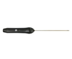
Smart air probe L=1000 mm SSV.1000P with built-in flash memory
from
14 214 ₽
Designed to measure the temperature of various materials by direct contact of the probe with the measuring object
The smart air probe L=1000 mm SSV.1000P with built-in flash memory is designed to measure the temperature of various materials by direct contact of the probe with the measuring object and transmitting the measured value via Bluetooth to devices with the ThermoMonitor. Android program is installed.
Operating conditions of the SZV.1000P smart probe
Ambient temperature, °C: -20...+55.
Relative humidity, %: not more than 80 at T=35 °C.
Atmospheric pressure, kPa: 86...106.
Functionality of the smart probe SSV.1000P
Measurement of physical quantities with a resolution of 0.01.
Recording of measured values at intervals from 5 seconds to 23 hours 59 minutes 59 seconds (only smart probes with built-in memory).
Transmitting data about measured physical quantities via Bluetooth to a device with the ThermoMonitor. Android program is installed.
Transmitting information about the state of charge of the built-in battery via Bluetooth to a device with the ThermoMonitor, Android program installed.
Automatic transition to sleep mode after 50 seconds.
The ability to connect an external power supply.
Possibility of calibration.
TEKHNO-AS
Kolomna
Produced in: Kolomna, Moscow region
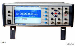
Universal frequency meter Ch3-86A
The frequency meter is capable of operating both independently and as part of automated measuring systems with an interface such as USB, RS-232 or IEEE-488 (CPC).
Technical specifications
Frequency and period of sinusoidal and video pulse signals (input A) 0.005 Hz - 100 MHz
Frequency of sinusoidal and video pulse signals (input to) 0.01 Hz - 100 MHz
Frequency of continuous sinusoidal oscillations (input C) (0.1 - 1) GHz
Frequency of continuous sinusoidal oscillations (input D) (0.6 - 17.85) GHz
Pulse duration 10 ns - 10000 s
The duration of the front, the decay of the pulses is 5 ns - 100 microseconds
Time interval from 0 to 10000 s
The frequency ratio of the two signals is up to 109
The average value of the carrier frequency of the pulse-modulated (IM) signal (input D) (0.6 - 17.85) GHz
Frequency measurement resolution 2x10⁻¹⁰ s/Rng
Phase difference of two synchronous sinusoidal signals from minus 180° to 180°
Measurement error of the phase difference of two synchronous sinusoidal signals ± 0.36° (from 1 kHz to 1 MHz)±3.6° (above 1 MHz)
Input signal level:
•for sinusoidal signal (inputs A, B) (0.03 - 7.0) V
•for video pulse signal (inputs A, B) (0.1 - 10.0) V
•for a sinusoidal signal (input C) (0.03 - 1.0) V
•for sinusoidal and IM signals (input D) 30 MW - 5 MW
Input resistance
•Inputs A, B (50±2.5) ohms; (1±0.1) MOm/100 pF
•inputs C, D (50±2.5) ohms
Nominal frequency value of the reference quartz oscillator 10 MHz
Relative error in the frequency of the quartz oscillator, no more than ± 2x10⁻⁷ in 12 months
Operating temperature range from minus 10 to 50 °C
AC power supply 220 V, 50 Hz; 220 V, 400 Hz
Power consumption, no more than 50 VA
Overall dimensions, mm 229x136x435.5
Weight, not more than 7.5 kg
TEKHNOYAKS
Moscow
Produced in: Moscow
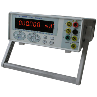
Voltmeter V7-82
Technical specifications:
DC voltage ,
Measuring range, 10 mv-1000V
Measurement error, ± 0.01%
AC voltage ,
Measuring range, 1 mV - 700 V
Measurement error, ± 0.4%
Frequency range, 20 Hz- 1 MHz
Direct current ,
Measuring range, 0.2 µA - 10 A
Measurement error, ± 0.15%
MNIPI
Minsk
Produced in: Belarus, Minsk
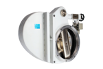
2ZVE-400R Electromechanical vacuum shutter with gearbox
The 2ZVE-400R vacuum shutter with electromechanical drive equipped with 400mm conditional passages is designed to overlap vacuum systems in the range of operating pressures from 1x10⁻⁶ to 1.07x10⁵ Pa (0.75x10⁻⁸ to 800 mm Hg). The 2ZVE-400R shutter is pendulum-type.
The 23VE-400R shutter is manufactured in climatic versions UHL (i.e. for moderate and cold climate) and O (i.e. general) 4 according to GOST standard 15150-69. The working environment is air and non–aggressive gases. It is not intended for use in fire hazardous and explosive industries. The 23VE-400R shutter meets the requirements of technical specifications TU 3648-040-00218526-2003. According to the method of protecting a person from electric shock, it belongs to Class I electrical equipment according to GOST 12.2.007.0-75.
Vakuummash
Kazan
Produced in: Kazan
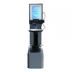
Metolab 602 Brinell Hardness Tester
The METOLAB 602 device is a stationary hardness tester according to the Brinell method (HBW scale) with automatic loading system and digital display. Among the features of the METOLAB 602 hardness tester are an electronic load value switch, an automatic turret, a large and bright LCD display with the ability to display the values obtained, as well as automatic translation of the results obtained into the Rockwell and Vickers scales. Additionally, it is worth noting the possibility of prompt printing of measurement results using a built-in printer.
The stationary METOLAB 602 Brinell hardness tester allows measurements of various materials, including steels, cast iron, non-ferrous metals, soft alloys, etc.
Due to its characteristics, the stationary METOLAB 602 Brinell hardness tester can be used in a wide variety of industries and production, as well as in educational institutions of various levels in the training of specialists.
The stationary METOLAB 602 Brinell hardness tester is included in the State Register of Measuring Instruments of Russia (GRSI) and comes with a certificate of primary verification (on request). The number in the GRSI is 65684-16.
Distinctive features of the stationary METOLAB 602 Brinell hardness tester:
Easy to operate and maintain the hardness tester;
Fully Russified menu;
A wide range of measured values – from 8 to 650 on the HBW scale;
The METOLAB 602 hardness tester has a built-in automatic switch of the applied load;
Large and bright LCD display, protected membrane keyboard;
Display of all necessary service information on the display;
Measuring the diameters of prints using the built-in digital microscope 20x;
The ability to quickly print out the measurement results on the built-in printer;
High accuracy and repeatability of measurements;
Automatic loading system.
Basic package of delivery:
Stationary METOLAB 602 Brinell hardness tester;
Microscope, 20x;
Indenter with carbide ball (10.0 mm; 5.0; 2.5) - 1 pc.;
Large flat table;
Small flat table;
V-shaped table;
Brinell hardness measures - 1 set;
User Manual.
Metolab
Moscow
Produced in: Moscow
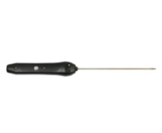
Smart probe air high-precision L=150 mm CVV.150
from
12 213 ₽
Designed to measure the temperature of various materials by direct contact of the probe with the measuring object
The high-precision air smart probe L=150 mm CVV.150 is designed to measure the temperature of various materials by direct contact of the probe with the measuring object and transmitting the measured value via Bluetooth to devices with the installed ThermoMonitor based on the Android program.
Operating conditions of the SZVV.150 smart probe
Ambient temperature, °C: -20...+55.
Relative humidity, %: not more than 80 at T=35 °C.
Atmospheric pressure, kPa: 86...106.
Functionality of the smart probe CVV.150
Measurement of physical quantities with a resolution of 0.01.
Recording of measured values at intervals from 5 seconds to 23 hours 59 minutes 59 seconds (only smart probes with built-in memory).
Transmitting data about measured physical quantities via Bluetooth to a device with the ThermoMonitor. The Android program is installed.
Transmitting information about the state of charge of the built-in battery via Bluetooth to a device with the ThermoMonitor, Android program installed.
Automatic transition to sleep mode after 50 seconds.
The ability to connect an external power supply.
Possibility of calibration.
TEKHNO-AS
Kolomna
Produced in: Kolomna, Moscow region
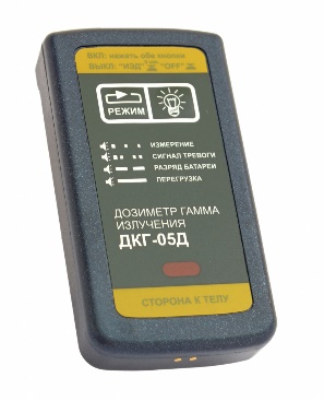
Individual gamma radiation dosimeter DKG-05D
Purpose:
measurement of individual dose equivalent (IED);
measurement of the power of the individual dose equivalent (MIED).
Doza
Zelenograd
Produced in: Moscow
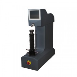
Metolab 103 Rockwell Hardness Tester
METOLAB 103 is an automatic electromechanical stationary device designed to measure the hardness parameters of various materials and products (steel, cast steel, alloy steel, non–magnetic metals, plastics and other materials) according to the Rockwell method, scales A, B, C, and also allows converting the results into Vickers, Brinell and Super-Rockwell scales. It is important to note that the stationary METOLAB 103 hardness tester has the ability to produce results on a PC in the form of Excel spreadsheets.
All measurements carried out by the METOLAB 103 hardness tester fully comply with current standards, including BS.EN 10109 and ISO716. The stationary METOLAB 103 hardness tester is listed in the State Register of Measuring Instruments of the Russian Federation under number 65128-16 and comes with a certificate of primary verification (on request).
Regulatory and technical documents establishing requirements for the METOLAB 103 hardness tester:
GOST 8.064-94 GSI. State verification scheme for hardness measuring instruments on the Rockwell and Super-Rockwell scales;
GOST 9013-59 Metals and alloys. Rockwell hardness measurement method. Scales A, B, C;
GOST 22975-78 Metals and alloys. Rockwell hardness measurement method at low loads (Super-Rockwell);
GOST 23677-79 Hardness testers for metals. General technical requirements.
Distinctive features of the stationary Metolab 103 Rockwell hardness tester:
Thanks to the special design of the measuring platform, it is possible to measure hardness in hard-to-reach places (grooves, holes, etc.);
Measurements are fully automated;
The ability to set the lower / upper limits of measurements, audible alarm when values exceed the set limits;
Statistical processing of results – output of minimum/average/maximum values, conversion of results into Brinell, Vickers, Super-Rockwell scales;
Correction for curvature when measuring a convex or cylindrical part;
Simple and intuitive control of the devices, the menu in Russian.
Basic delivery package:
Stationary Metolab 103 Rockwell hardness tester;
Indenter with a ball (1.5875 mm) - 1 pc.;
Spare ball (1.5875 mm) – 3 pcs.;
Conical diamond indenter (120°) - 1 pc.;
Flat table SP1 (60 mm);
V-shaped prismatic table SRP1 (40 mm);
Rockwell Hardness measures;
User Manual.
Metolab
Moscow
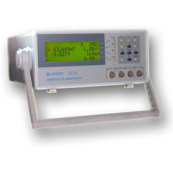
Immitance meter E7-20
Technical specifications:
Wide frequency range 25 Hz–1 MHz
Capacity (10-15-1) F
Inductance (10-11-104) Gn
Resistance (10-5-109) Ohms
Conductivity (10-11-10) Cm
Modulus of complex resistance (10-5-109) ohms
Reactance (10-5-109) Om
Phase shift angle -90° – +90°
Q factor, loss factor 10-4-104
Leakage current (10-8-10-2) A
The error is ±0.1%
Offset voltage 0 – 40 V (external up to 120 V)
Measuring signal level (0.04 – 1) V
RS-232C interface
Mathematical processing of measurements
Dimensions, weight: 127x298x300 mm, 4 kg
Power supply ~220 V, 20 VA
MNIPI
Minsk
Produced in: Belarus, Minsk
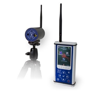
Laser dosimeter LD-07
from
125 000 ₽
LD-07 laser dosimeters are designed to measure the energy exposure and irradiance of scattered or reflected laser radiation in automatic mode, as well as to analyze the measurement results in accordance with current sanitary norms and regulations No. 580491, IEC 825-1-93 in order to determine the danger of radiation to the human body.
NMT-ZASHCHITA
Moscow
Produced in: Moscow
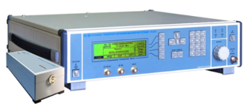
High-frequency signal generator G4-235, G4-236
Created on the basis of the G4-230 generator. Remote frequency converters extend the frequency ranges up to 53.57 GHz (G4-235) and up to 78.33 GHz (G4-236).
The generators are capable of operating both independently and as part of automated measuring systems with USB and IEEE-488 (CPC) interfaces.
Technical specifications
The frequency range at the output of the base unit is from 5 to 20 GHz
Frequency range at the output of the frequency converter (G4-235) from 37.5 to 53.57 GHz
The frequency range at the output of the frequency converter (G4-236) is from 53.57 to 78.33 GHz
Frequency tuning discreteness 0.001 Hz
The main error of the frequency setting is ± 3x10⁻⁷ Hz
The range of setting the signal power level at the output of the base unit is from minus 110 to 13 dBm
The range of setting the signal power level at the output of the frequency converter (G4-235) is from 0 to 13 dBm
The range of setting the signal power level at the output of the frequency converter (G4-236) from 0 to 10 dBm
The basic error of setting the reference power level is ± (1.0 – 2.5) dB
Metrological characteristics of the generator in FM operation mode:
- frequency range of the modulating signal from 1 Hz to 20 kHz
- frequency deviation setting range (taking into account the carrier frequency value) from 1 Hz to 200 kHz
- the main error of the frequency deviation setting is ± (5 – 18)%
Metrological characteristics of the generator in AM operation mode:
- frequency range of the modulating signal from 0.05 to 5.0 kHz
- the range of setting the amplitude modulation coefficient from 1 to 50 %
- the basic error of setting the amplitude modulation coefficient ± (0.15 M + 0.2)%
Metrological characteristics of the generator in the IM operation mode:
- the duration range of modulating pulses from 100 ns to 20 s
- the range of the modulating pulse repetition period from 140 ns to 30 s
- the difference in the duration of the output RF pulses from the duration of the modulating pulses ± 100 ns
Operating temperature range from 5°C to 40 °C
AC power supply 220 V, 50 Hz
Power consumption, no more than 150 VA
Overall dimensions, mm 498x136x487
Weight, not more than 20 kg
TEKHNOYAKS
Moscow
Produced in: Moscow
