Catalog
Search
5 products
View:
- Selected: 0Areas of use
- Selected: 1Item names
- Selected: 0Manufacturer
- Selected: 0Made in
- Selected: 0Additional
View:
5 products

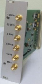
Amplifier module MUS-04
The module uses connectors of the SMA type. At the request of the customer, any combination of output signals is possible. When installing two amplifier modules in the above devices, the total number of output signals increases to twelve.
Ruknar
Nizhny Novgorod
Produced in: Nizhny Novgorod

RF power amplifiers
Basic electrical characteristics
1. Operating frequency, MHz 63.85 MHz ± 0.2
2. Rated output power,
at least, kW 1 1
3. Deviation of the amplitude characteristic from the linear one, no more than, dB 2
4. Relative level of harmonic
components of the output signal, no more than, dB minus 20 1, 2
5. Nominal level of the input RF signal, dBm 3
6. Input and output impedance, ohms 50
7. VSWR RF input, no more than 2
8. Permissible VSWR RF load, no more than 3
9. Pulse mode of operation
10. Duration of the radio pulse, no more than, ms 100
11. Effective borehole, at least 2
12. Rise/fall time of the RI amplitude,
no more than, ns 500 1, 4
13. Noise, no more than, dB/Hz minus 154 1, 5
Moshchnaya radiotekhnika
Voronezh
Produced in: voronezh

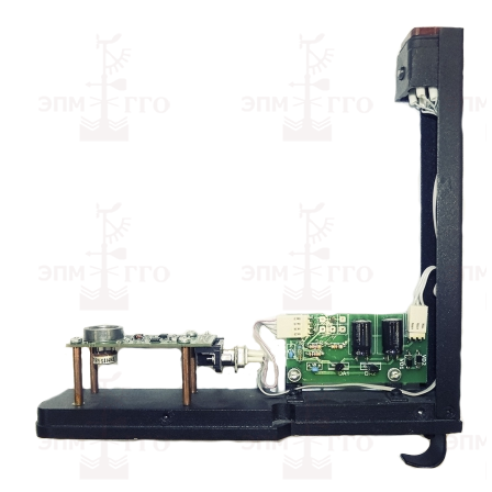
Photo Amplifier for DVO, IVO, RVO
from
144 600 ₽
EMPGGO
Saint Petersburg
Produced in: Saint Petersburg
Microassembly RB1S8KN009
Two-channel analog switch with signal summation function
Designed for use in oscilloscopes with a bandwidth up to 350 MHz.
Technical specifications:
The value of the voltage between the outputs of the switch at load resistance RN = (50 ± 2.5) ohms and opening voltages UU1 = (2.0 ± 0.2) V and locking UU2 = (4.2 ± 0.2) V channels supplied alternately to the corresponding inputs (start 1, start 2) of the switches must be:
in the absence of an input signal
from minus 0.1 to plus 0.1 V
with an input signal UC = (0.3 ± 0.05) V supplied to one of the inputs of the open channel
(0.45 ± 0.1) V
with an input signal UC = (0.3 ± 0.05) V supplied to one of the inputs of both open channels
(0.45 ± 0.1) V
MNIPI
Minsk
Produced in: Belarus, Minsk
AF011B Microassembly
A high-speed signal limiter amplifier.
Designed for use in electronic counting frequency meters.
Description:
The magnitude of the input signals for selecting the switch input and inverting the signal of the limiter amplifier at a supply voltage of ± 5 V:
- logical "0"
not more than 0.2 V;
- logical "1"
at least 4.8 V.
The value of the input signals of switching on / off the switch at a supply voltage of ± 5 V:
- logical "0"
no more than 3.3 V;
- logical "1"
at least 4.1 V.
The magnitude of the output signals of the switch at a supply voltage of ± 5 V and a load of 300 ohms connected to zero potential:
- logical "0"
from 3.1 V to 3.4 V;
- logical "1"
from 4.0 V to 4.3 V.
The minimum input voltage of the sinusoidal shape in the frequency range from 10 Hz to 200 MHz should be no more than 30 mV.
The maximum input voltage of the sinusoidal shape in the frequency range from 10 Hz to 200 MHz must be at least 1 V.
The value of the supply voltage:
- positive
5±0.2 V;
- negative
-5±0.2 V.
The current consumption should be no more than:
- from a positive power source
110 mA;
- from a negative power supply
35 mA.
MNIPI
Minsk
Produced in: Belarus, Minsk
