Catalog
Search
1059 products
View:
- Selected: 1Applying
- Selected: 0Names
- Selected: 0Manufacturer
- Selected: 0Made in
- Selected: 0Additional
View:
1059 products
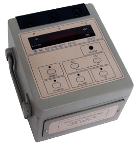
Megaohmmeter E6-23
Designed to measure the insulation resistance of electrical circuits that are not under voltage, in the range from 10 kOhm to 100 Gom.
Technical specifications:
Ranges: 10kOhm–100gohm
Measurement error: ±(1.5–2.5)%
Test voltage: 2500 V
3 digit digital indicator
Built-in battery
Dimensions, weight: 150x170x200 mm, 4 kg
Power supply: ~110, ~220, 15 VA, 12V battery
Operating temperature: -20 °C – +50 °C
MNIPI
Minsk
Produced in: Belarus, Minsk
A set of measures of electrical resistance H2-2
Designed for storing and transmitting the size of a resistance unit, as well as for checking and calibration of working resistance measures and complex resistance meters with a four-pair or five-clamp connection scheme in the frequency range from DC to 10 MHz.
Description:
Each of the resistance measures H2-2 is a precision resistor, in series and in parallel to which fitting resistors are connected, placed in an aluminum housing.
The measures have a four-pole connection scheme. Four BNC type connectors (plugs) are located on the wall of the housing. The distance between the connectors is 22 mm.
In measures of 100 kOhm and 1 mOhm, it is possible to adjust the value of the time constant of the measure using a tuning capacitor.
MNIPI
Minsk
Produced in: Belarus, Minsk
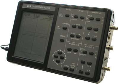
Digital oscilloscope C8-39
It is designed to study periodic signals in the frequency band 0-50 MHz and single electrical signals by registering them in digital memory with a sampling frequency of up to 50 MHz, observing their shape on a liquid crystal display (LCD), measuring the amplitude and time parameters of the signal under study.
Technical specifications:
Vertical deviation :2
Number of channels 0-50 MHz
Rise time of PH ≤ 7.0 ns
Input impedance 1 ± 0.03 mOhm, 25 pF
Deviation coefficients of 5 mV/div - 2 V/div (step 1-2-5)
The maximum input voltage is 100 V
With a divider of 1:10 250 V
The error of amplitude measurements is a≤ 2 %
5 mV...2 V; 10 ns...2 s/del.
ADC: 2 channels, 50 MHz, 8 bits
Equivalent sampling rate of 2.5 GHz
Marker measurements U: ±2.5%, T: ±1.5%
Pre-launch 8 screens,
post-launch 150 screens
Simultaneous observation of 2 signals
Cursor measurements DU and DT
Averaging modes and automatic DU and DT measurements
LCD screen - 320x240 dots (monochrome)
RS 232C interface
Dimensions, weight 176x280x80 mm, 3 kg
Power supply: +12V, 230B
MNIPI
Minsk
Produced in: Belarus, Minsk
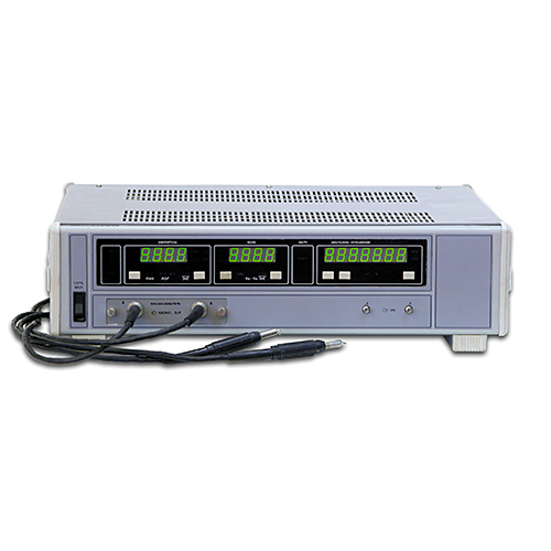
Phase difference meter and level ratio FC2-40/1
NNPO im. M.V.Frunze
Nizhny Novgorod
Produced in: Nizhny Novgorod
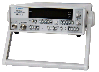
Frequency meters Ch3-81, Ch3-81/1
Designed to measure the frequency or single and averaged period of sinusoidal and pulse signals, as well as to measure the pulse duration and frequency ratio, with a guaranteed measurement error of up to 10-7za year.
Description:
Ch3-81 (inputs A, B, C) – range 0.1 Hz–2.5 GHz
Ch3-81/1 (inputs A, B) – range 0.1 Hz–200 MHz
Frequency measurement, frequency ratios
Measurement of the period, duration of 1 microsecond–10000 s
Signal level 30 mV–10 V (eff.), pulse up to 30 V
Thermostated quartz 5 MHz: ±10-7 (year) ±7.5X10⁻⁹(day)
Frequency temperature departure: ±2.5X10⁻⁸ (+5...+40 °C)
Number of averaged periods: 1-104
Timestamps 10-7-10-3 s
RS-232 interface
8-bit SD indicator
Dimensions, weight 80X220X300 mm, 3 kg
Power supply: ~ 220V, 20V
MNIPI
Minsk
Produced in: Belarus, Minsk
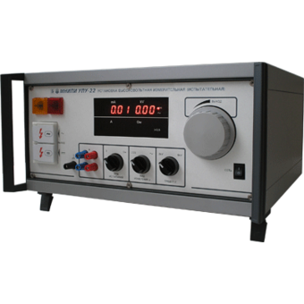
High-voltage test unit UPU-22
Technical specifications:
Output voltage (DC and AC), 0 - 2 kV; 0 - 5 kV
Built-in AC power supply, 10 - 25 A
The amplitude value
of the DC voltage ripple relative to the set
output voltage of 5 kV at idle is not more than ± 5%
Error in setting the output voltage, ± 3%
Protection tripping current, 101 -- 140 mA
Load current of DC and AC output voltage, not less than 1 mA
The limit of measuring the resistance of the integrity of the circuit connection, 0, 01 – 0.10 ohms
MNIPI
Minsk
Produced in: Belarus, Minsk
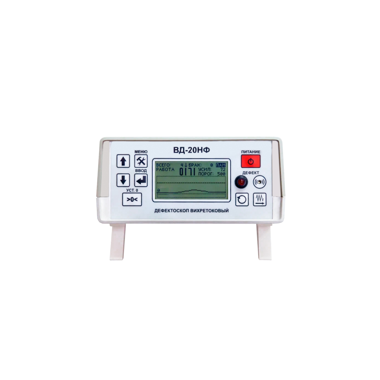
VD-20NF Eddy Current Flaw Detector
The principle of operation of the VD-20NF eddy current flaw detector
The principle of operation of the VD-20NF flaw detector is based on the generation of eddy currents on the surface of the controlled part and subsequent analysis of the signal at the output of the converter, which correlates with the characteristics of the active secondary field.
The device consists of two main blocks: electronic one and electromechanical one, in which an eddy current converter of transformer type is installed. The controlled products (bearing rollers) enter through the input tray into the electromechanical unit of the flaw detector, where they move sequentially and fall under the pressure rollers of the overhead converter holder. The clamping mechanism is adjusted to each size of the rollers, so as to ensure tight contact with the curved surface and fix the tip of the transducer at the required distance from it.
The detection of defects occurs due to the imbalance of the converter when it is located above the surface of the controlled product, caused by the interaction of the primary electromagnetic field generated by the converter with the secondary electromagnetic field of eddy currents induced in the controlled product by the primary field. When cracks are detected, the electronic unit of the flaw detector gives sound and light warning signals, and also triggers the electromagnet of the sorter, which directs the controlled roller into the tray for defective products. In the absence of defects, the controlled roller is directed towards the output tray of the flaw detector.
Design features and advantages
The VD-20NF eddy current flaw detector is equipped with removable input and output trays, power-on switches and a drive for feeding controlled products to the converter, as well as handrails for convenient transportation of the unit.
The mechanisms of the electromechanical unit are protected by a frame made of steel plates. The electronic unit of the flaw detector is portable and can be installed both on the top panel of the electromechanical unit and on the surface of the desktop. Controls and indications of defect detection are located on the front panel of the electronic unit. The delivery package also includes a power adapter for the electronic unit and a tuning sample. The advantages of the VD-20NF flaw detector include:
high reliability (the service life of the flaw detector is more than 10 years);
it is easy to set up and operate;
it has several types of defect detection alarms;
the high probability of detecting defective products (at least 99.9%);
low number of false positives (less than 5%).
Scope of application
According to the current standards of safety and product quality control during repair work in locomotive depots and repair plants, bearing rollers that have passed visual inspection and are recognized as suitable for further operation according to the criteria of geometry and condition of the working surface are subject to mandatory additional control using eddy current flaw detection to detect fatigue cracks invisible during visual inspection on the rolling surface of the rollers. The VD-20NF eddy current flaw detector allows for quality control and automatic disassembly of bearing rollers of various shapes and sizes both in laboratory and factory conditions in full compliance with the requirements of the regulatory documents of Rosstandart and the methods of performing control measurements used in JSC "Russian Railways".
RII MNPO SPEKTR
Moscow
Produced in: Moscow
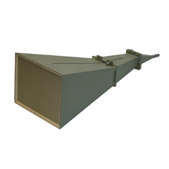
Measuring antenna P6-23M
Technical specifications:
Frequency range (0.85 - 17.44 GHz)
Standing Wave Coefficient (SWR) < 1.7
Effective area at least in the frequency range - from 0.85 to 15 GHz > 150 cm2 - from 15 to 17.44 GHz > 110 cm2
The margin of error of the effective area in the frequency range, no more - from 0.85 to 8.5 GHz ± 20% - from 8.5 to 17.44 GHz ± 15%
Orthogonal polarization signal level -25 dB
The level of the side lobes, no more than -10 dB
Ambient temperature -50°C - 50°C
Gabbar dimensions (HxWxD) 887x351x265 mm
Weight 6,8 kg
MNIPI
Minsk
Produced in: Belarus, Minsk
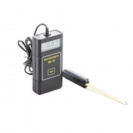
MX-10 Magnetometer
from
67 000 ₽
The MX-10 magnetometer is an auxiliary tool for conducting magnetic powder control using permanent magnets, rectified current electromagnets by the applied field method, as well as for monitoring by the residual magnetization method according to the requirements of the current regulatory documentation.
The MX-10 magnetometer meets the requirements in the field of non-destructive testing for the main industries: nuclear, energy, oil and gas complex, general and special engineering, railway transport, aerospace industry, elevator and crane facilities, etc.
Magnetometer MX-10 is an electronic measuring unit with a remote measuring converter, which is based on the Hall effect. The design of the device allows measuring both the normal and tangential component of the magnetic induction vector directly on the surface of the part. The measured value of the magnetic field induction value is displayed on the digital indicator of the electronic unit.
Features and Benefits
The updated version of the MX-10 magnetometer has a modern element base, which has significantly improved its performance, reduced error and expanded the measurement range (see the Table of Technical characteristics).
The device is capable of operating in two modes:
Constant measurement mode. This is convenient when carrying out a large number of measurements over a short period of time.
Automatic shutdown mode 1 minute after measurement. It allows you to save the charge of the device, which is especially important in the field.
A thermal compensation circuit ensures stable measurement readings at any temperature change.
Other features include:
The small dimensions of the Hall measuring transducer for the MX-10 magnetometer make it possible to measure the induction of the magnetic field in grooves, grooves, angular transitions, i.e. in those areas of the controlled product that are stress concentrators and are most dangerous from the point of view of cracking;
A wide range of measurements of the magnitude of the magnetic field induction;
The smallest measurement error among analogues in the entire operating temperature range;
Convenience of measurement by a remote measuring transducer in various planes;
Low power consumption and, as a result, long working time;
Low cost compared to similar models on the market;
Compact dimensions;
Manufacturer's warranty – 12 months;
The device is included in the state register of measuring instrument RU.C.27.004.A No. 36079 dated 01.09.2009 and has undergone a verification procedure. Magnetometer MX-10 (milliteslameter) it is also included in the register of measuring instruments, test equipment and measurement methods used in JSC "Russian Railways".
Scope of application
1. Verification of the magnetization modes of controlled parts using permanent magnets, rectified current electromagnets by the applied field method, as well as during the control by the residual magnetization method, by measuring the tangential and normal components of the magnetic field strength vector at one or more points on the surface of these parts. The number of points at which the magnetic field strength is measured and their location on the controlled surface depend on the shape of the part, as well as on the type and design of the magnetizing device used.
2. Control of the magnetization of parts before welding. During electric arc welding of non-magnetized parts, the effect of "magnetic blowing" is observed, i.e. the deviation of the electric arc from the axis of the electrode, the wandering of the arc end along the product, which leads to metal splashing during welding, deterioration of the seam quality. Therefore, before welding, it is necessary to measure the level and direction of magnetization of the parts and demagnetize them if necessary.
3. Verification of the residual magnetization after magnetic powder inspection. Demagnetization and verification of the residual magnetization of responsible, rubbing parts, as well as parts in contact with them after assembly, is prescribed in the requirements of the IPC and is a technological stage of control.
4. Magnetization control before assembling various structures. Magnetized parts can affect the operation of automation devices, cause errors in the readings of instruments, equipment. Magnetization can cause the accumulation of wear products in the movable joints, cause a negative effect on subsequent technological operations. Due to possible undesirable consequences, the parts are demagnetized and the quality of their demagnetization is checked.
5. Control of gas and water meters. Housing and utilities enterprises may also be interested in the device. It is known that existing gas or water flow meters can be easily "deceived" with the help of strong permanent magnets that reduce the rotation speed of the flow sensors. There are different ways to detect such theft. One of them is the control of the residual magnetization of the counters using magnetometers. The measured value should not significantly exceed the Earth's magnetic field, otherwise it can be concluded that there was unauthorized interference with the operation of the device.
Main technical characteristics
Measuring range, MT from 0.1 to 100
The limits of the permissible basic absolute measurement error, MT D = 0.02 VI + 0.05,
where VI is the magnetometer readings in MT
Power supply battery type: PP3 (nine-volt battery)
Consumption current, mA, no more than 15
Duration of continuous operation
(from fully charged batteries), h, at least 20
Overall dimensions, mm:
– electronic unit (LxWxH) 120x60x25
– Measuring transducer (Diameter x Length) 18x173
Weight, g, not more than 160
Ambient operating temperature, °C -10...+40
RII MNPO SPEKTR
Moscow
Produced in: Moscow

VD-7.2×3.4
A flexible waveguide is a piece of high-quality dielectric, which ends with transitions to standard waveguides with flanges.
For ease of operation, the waveguide is protected by an elastic shell.
Basic properties
Manufacturability of the connection;
Small losses and VSWR;
Economy.
Operating conditions
Operating temperature range from 5 to 50 ° C;
The relative humidity of the air is up to 98% at a temperature of 25 ° C.
Technical specifications
Waveguide cross section, mm 7.2×3.4
Flange type according to GOST RV 51914-2002
Frequency range, GHz 25.95-37.50
VSWR 1.25
Losses, dB 2.0
Length, mm* 500
TEKHNOYAKS
Moscow
Produced in: Moscow
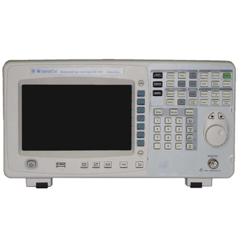
Spectrum Analyzer S4-101
Technical specifications:
The operating frequency range of the monitored signals is from 9·103 to 3·109 Hz
The analyzer has a zero band and a viewing band in the range from 100 Hz to 3 GHz
Limits of permissible error of setting the viewing band ± 1 %
The scan range is set from 10 ms to 3000 s in all modes except the zero band of view, and from 20 microseconds to 3000 s in the zero band of view mode
The bandwidth of the RFP at the level of minus 3 dB is selected in the range from 100 Hz to 1 MHz in increments of 1, 3, 10
The squareness coefficient of the FPC at the level of minus 60 dB / minus 3 dB is not more than 5:1
The reference level setting range is from plus 30 dBm to minus 100 dBm. Installation step 1 dB
Limits of the permissible basic error of setting the reference level ± 1 dB
The limits of the unevenness of the amplitude-frequency response (frequency response) of the analyzer in the frequency range from 100 kHz to 3 GHz ± 1 dB
Maximum allowable input power is 30 dBm (1 W)
Limits of the permissible basic error of measuring the signal level due to the nonlinearity of the logarithmic scale ± 1 dB
Limits of the permissible basic error of measuring the signal level due to switching of the input attenuator ± 1 dB
Limits of error in measuring the signal level due to switching filters, ± 0.2 dB relative to the 1 kHz filter
The average level of intrinsic noise at the FPC bandwidth of 100 Hz, the video filter band of 10 Hz and the input attenuator of 0 dB:
- in the range from 100 kHz to 20 MHz minus 75 dBm
- in the range from 20 MHz to 1.5 GHz minus 110 dBm
- in the range from 1.5 to 3 GHz minus 105 dBm
The input impedance of the analyzer is 50 ohms
The voltage standing wave coefficient (VSWR) of the input with an input attenuator greater than 10 dB, no more:
- 1.5 in the frequency range from 10 MHz to 2.5 GHz
- 1.8 in the frequency range from 2.5 GHz to 3 GHz
Diagonal screen size 21.5 cm
Screen resolution 800x480
USB interface
Overall dimensions – 398x220x150 mm
Weight not more than 6.5 kg
MNIPI
Minsk
Produced in: Belarus, Minsk
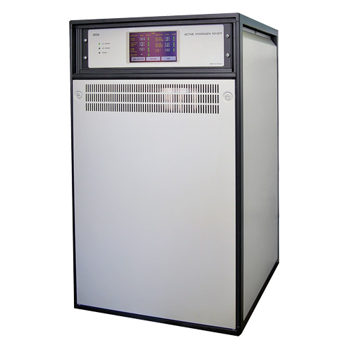
Frequency and time standard hydrogen H1-95
NNPO im. M.V.Frunze
Nizhny Novgorod
Produced in: Nizhny Novgorod Region
