Catalog
Search
1059 products
View:
- Selected: 1Applying
- Selected: 0Names
- Selected: 0Manufacturer
- Selected: 0Made in
- Selected: 0Additional
View:
1059 products
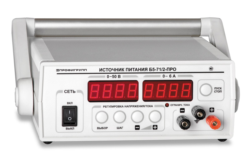
Pulse DC power supply B5-71/5-PRO
1 supp.
Regulated switching power supplies with highly stable output characteristics
Digital display of set and actual value, voltage and current (4 digits, LED)
Electronic load switching on/off
Protection against overload, short circuit, overheating and reverse polarity
Low ripple output voltage less than 2mV
Low ripple output current less than 5mA
Minimum discreteness of setting output voltage and current 0.007/0.005
Operating modes: stabilization U and I, dynamic load
RS-232 interface
DIPAUL
Saint Petersburg
Produced in: Saint Petersburg
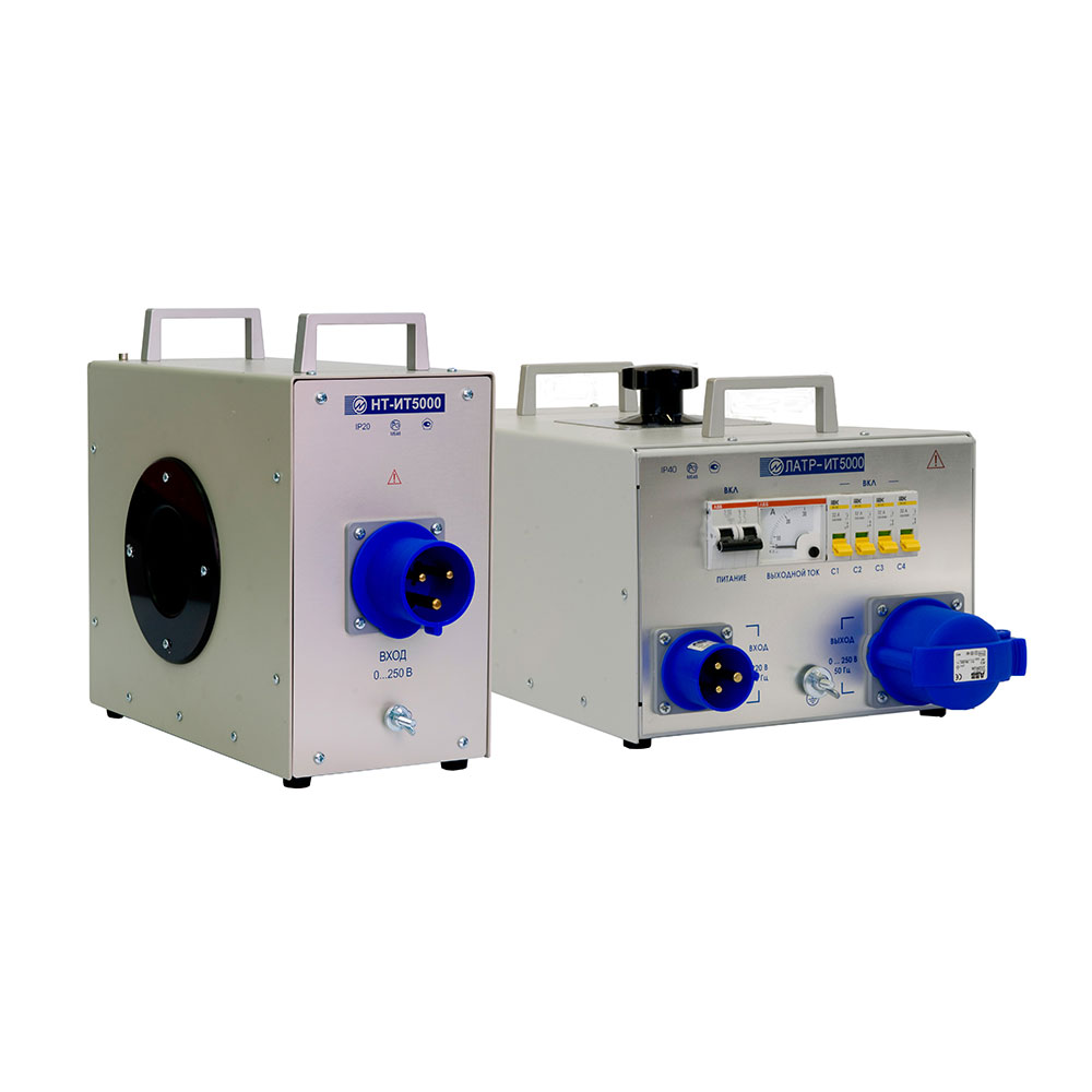
IT5000 Adjustable current source up to 6 kA
Marsenergo
Saint Petersburg
Produced in: Saint Petersburg
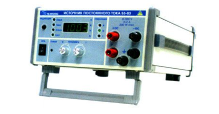
DC power supply B5-83
The B5-83 DC power supply is designed to provide constant
voltage and current to devices and equipment during the development, production,
operation and repair of electronic devices.
- Allows harsh operating conditions
- Wide range of currents and voltages at a maximum power of 200 watts
Technical specifications
Output voltage setting range from 3 to 300 V
Output current setting range from 0.05 to 2 A
Electrical output power, not more than 200 watts
The main error of the output voltage setting is ± 2 V
The main error of setting the output current is ± 0.02 A
Additional error in setting the output voltage caused by a deviation of the mains voltage from the nominal value by ± 10% ± (0.0001 · Uust + 3 mV)
Additional error in setting the output voltage caused by a change in the load current from 0.9 of the maximum value to zero ± (0.0002 · Uust + 10 mV)
Additional error in setting the output current caused by a deviation of the mains voltage from the nominal value by ± 10% ± (0.0002 · Iust + 1 mA)
Additional error in setting the output current caused by a change in the load voltage from 0.9 of the maximum value to zero ± (0.0005 · Iust + 2 mA)
The change in the output voltage in the voltage stabilization mode with a deviation of the ambient temperature in the operating temperature range by ± 10 ° C, not more than ± 250 mV
Change of the output current in the current stabilization mode with a deviation of the ambient temperature in the operating temperature range by ± 10 ° C, not more than ± 10 mA
Operating temperature range from minus 10 to 50 °C
AC power supply 220 V, 50 Hz
Power consumption, no more than 350 VA
Overall dimensions, mm 240x128x313
Weight, not more than 5.5 kg
TEKHNOYAKS
Moscow
Produced in: Moscow
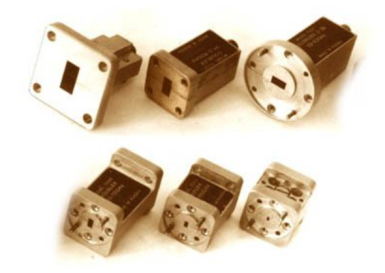
UCHX3-53
Basic properties:
Wide frequency range;
Sufficiently large output power;
High level of suppression of side harmonics of the input signal;
Low phase noise value;
Relatively simple technical solutions:
- synchronization and frequency stabilization,
- stabilization and adjustment of the output power level,
- implementation of amplitude and frequency modulation modes;
Do not require external bias diodes.
Operating conditions:
Operating temperature range from minus 10 to 50 °C;
The relative humidity of the air is up to 98% at a temperature of 25 ° C.
Technical characteristics
Input/output frequency range, GHz 12,50- 17,86 / 37,50- 53,57
Losses (max.), dB 17
Input power level, 15-20 dBm
Unevenness of output power (Rvh. = 20 dBm), dB ± 2.0
The level of parasitic harmonics of the input signal at the output (min.), dBn 20
Output VSWR (max.) 2.0
Connector type:
• Input Coax. 3.5/1.5 mm (socket)
• Output Waveguide 5,2x2,6 mm
Overall dimensions, mm 34x20x20
Weight, g 60
TEKHNOYAKS
Moscow
Produced in: Moscow
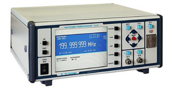
Universal frequency meter Ch3-95
The frequency meter is capable of operating both autonomously and as part of automated measuring systems with interfaces such as BUSB, RS-232, ETNET and IEEE-488 (CPC).
Technical specifications
Frequency and period of sinusoidal signals (inputs A, B) 0.001 Hz - 300 MHz
Frequency and period of video pulse signals (inputs A, B) 0.001 Hz - 300 MHz
Frequency of continuous sinusoidal oscillations (input C) (37.5 – 78.33) GHz
Pulse duration 5 ns - 1000 s
The duration of the front, the decay of the pulses is 5 ns - 100 microseconds
Time interval from -1000 to 1000 s
Frequency measurement resolution 2x10⁻¹⁰ s/Rng
Setting range of trigger levels (inputs A, B) from -2 to 2 V
The error of setting the trigger levels (inputs A, B) ± 0.01 V
Input signal level:
•for sinusoidal signal (inputs A, B) (0.03 - 10.0) V
•for video pulse signal (inputs A, B) (0.1 - 10.0) V
•for a sinusoidal signal (input C) 0.5 MW - 5 MW
Input resistance
•Inputs A, B (50±2.5) ohms; (1±0.1) MOm/100 pF
•Input With (50±2.5) ohms
Nominal frequency value of the reference quartz oscillator 10 MHz
Relative error in the frequency of the quartz oscillator, no more than ± 2x10⁻⁷ in 24 months
Operating temperature range from minus 10 to 40 °C
AC power supply 220 V, 50 Hz
Power consumption, not more than 100 VA
Overall dimensions, mm 299x130,5x433
Weight, not more than 8.5 kg
TEKHNOYAKS
Moscow
Produced in: Moscow
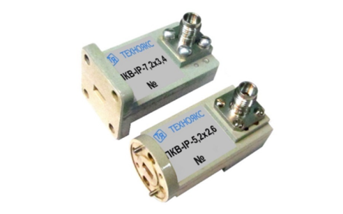
PKV-IB-5,2×2,6
Basic properties
Wide frequency range;
Small VSWR values.
Operating conditions
Operating temperature range from minus 10 to 50 ° C;
The relative humidity of the air is up to 98% at a temperature of 25 ° C.
Technical specifications
Waveguide cross section, mm 5.2×2.6
Type of coaxial connector (according to GOST RV 51914-2002) IB
Frequency range, GHz 37.50-50.00
VSWR 1.45
TEKHNOYAKS
Moscow
Produced in: Moscow
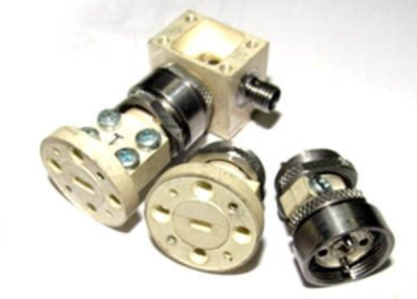
PS-78 (waves.)
Strobe converters are used as input devices of radio measuring equipment: amplifasometers, frequency meters, spectrum analyzers, circuit analyzers, etc.; in systems of synchronization and frequency stabilization of microwave generators, heterodynes, frequency synthesizers.
Basic properties:
Wide frequency range;
Minimal losses and uneven conversion;
High "decoupling" of channels;
Large dynamic range of input signals;
Harsh operating conditions
Operating conditions
Operating temperature range from minus 10 to 50 °C;
Relative humidity up to 98% at a temperature of 25 ° C.
Technical specifications
Frequency range:
• Microwave signal, GHz 37.5-78.33
• heterodyne, GHz 2.0-6.0
• IF, MHz 0-1000
Conversion losses *>, 30-40 dB by the 20th garm.
The power level of the heterodyne, dBm 20-22
Connector type:
• Microwave signal input P-waveguide with transitions to 5,2x2,6 and 3,6x1,8 mm
• 1HR heterodyne input
• IF output two woofer inputs
TEKHNOYAKS
Moscow
Produced in: Moscow
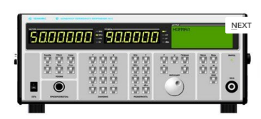
AC voltage calibrator H5-5
The calibrator is capable of operating both autonomously and as part of automated measuring systems with interfaces such as USB, RS-232, IEEE-488 (CPC).
Technical specifications
Ranges of reproduction of alternating electric voltage in the frequency range:
- from 10 Hz to 100 MHz from 3 MV to 3 V
- over 100 MHz to 2000 MHz from 30 MV to 3 V
Errors in the reproduction of alternating electric voltage in the frequency range:
- from 10 Hz to 100 kHz ± (0.066 – 0.8)%
- over 100 kHz to 100 MHz ± (0.85 – 2.5)%
- over 100 MHz to 700 MHz ± (1.5 – 12.7)%
- over 700 MHz to 2000 MHz ± (4.3 -14.0)%
General characteristics:
Operating temperature range from 5 to 40 °C
AC power supply 220 V, 50 Hz
Power consumption, no more than 180 VA
Overall dimensions, mm 495x217x411
Weight, not more than 24 kg
TEKHNOYAKS
Moscow
Produced in: Moscow
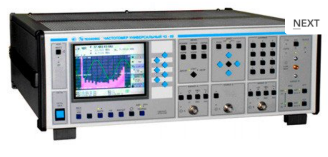
Universal frequency meter Ch3-89
The frequency meter is able to work both independently and as part of automated measuring systems with interfaces such as USB or RS-232.
Technical specifications
Frequency and period of sinusoidal signals (inputs A, B) 0.001 Hz - 150 MHz
Frequency of video pulse signals (inputs A, B) 0.001 Hz - 100 MHz
Frequency of continuous sinusoidal oscillations (input C) (0.1 - 1) GHz
Frequency of continuous sinusoidal oscillations (input D) (1 - 37.5) GHz
Carrier frequency of a continuous signal with frequency modulation (FM) (input D) Fh = (1 - 18) GHz, Fm = 100 Hz-100 kHz; frequency deviation from 10 kHz to 10 MHz
Carrier frequency of a continuous signal with amplitude modulation (AM) (input D) Fh = (1 - 18) GHz, Fm = 100 Hz - 100 kHz; AM factor up to 100%
Carrier frequency of a continuous radio pulse sequence (IM) signal (input D) Fn = (1-37.5) GHz, from 0.15 microseconds to 1ms, Fsl from 100 Hz to 3 MHz, from 2 to 103
Pulse duration 10 ns – 0.1 s
Time interval from -10 to 10 s
The duration of the front, the decay of the pulses is 5 ns - 100 microseconds
Phase difference of two synchronous sinusoidal signals from minus 360° to 360°
The measurement error of the phase difference of two synchronous sinusoidal signals is ± 0.36° (from 1 kHz to 1 MHz) ± 3.6° (above 1 MHz)
Input signal level:
•for sinusoidal signal (inputs A, B) (0.03 - 7.0) V
•for video pulse signal (inputs A, B) (0.1 - 10.0) V
•for a sinusoidal signal (input C) (0.03 - 1.0) V
•for sinusoidal and IM signals (input D) 10 MW (from 1 to 8 GHz); 40 MW (sv. 8 to 18 GHz); 50 MW (sv. 18 to 37.5 GHz).
The nominal frequency value of the reference quartz oscillator is 10 MHz
Relative error in the frequency of the quartz oscillator, no more than ± 2x10⁻⁷ in 12 months
Operating temperature range from 5 to 40 °C
AC power supply 220 V, 50 Hz
Power consumption, no more than 100 VhA
Overall dimensions, mm 496x174x459
Weight, not more than 16 kg
TEKHNOYAKS
Moscow
Produced in: Moscow
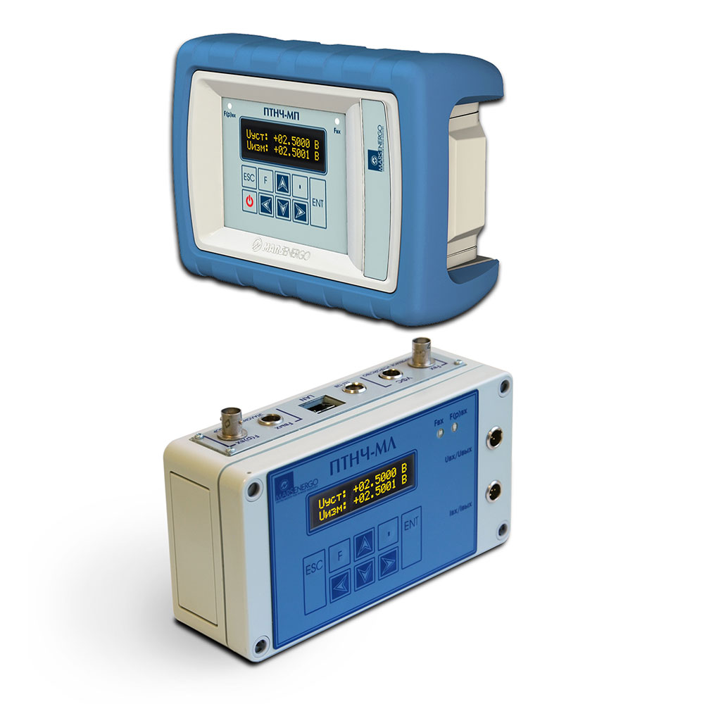
PTNCH-MP Calibrator/measuring device for unified DC signals
Marsenergo
Saint Petersburg
Produced in: Saint Petersburg
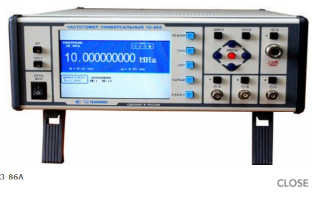
Universal frequency meter Ch3-86A
The frequency meter is capable of operating both independently and as part of automated measuring systems with an interface such as USB, RS-232 or IEEE-488 (CPC).
Technical specifications
Frequency and period of sinusoidal and video pulse signals (input A) 0.005 Hz - 100 MHz
Frequency of sinusoidal and video pulse signals (input to) 0.01 Hz - 100 MHz
Frequency of continuous sinusoidal oscillations (input C) (0.1 - 1) GHz
Frequency of continuous sinusoidal oscillations (input D) (0.6 - 17.85) GHz
Pulse duration 10 ns - 10000 s
The duration of the front, the decay of the pulses is 5 ns - 100 microseconds
Time interval from 0 to 10000 s
The frequency ratio of the two signals is up to 109
The average value of the carrier frequency of the pulse-modulated (IM) signal (input D) (0.6 - 17.85) GHz
Frequency measurement resolution 2x10⁻¹⁰ s/Rng
Phase difference of two synchronous sinusoidal signals from minus 180° to 180°
Measurement error of the phase difference of two synchronous sinusoidal signals ± 0.36° (from 1 kHz to 1 MHz)±3.6° (above 1 MHz)
Input signal level:
•for sinusoidal signal (inputs A, B) (0.03 - 7.0) V
•for video pulse signal (inputs A, B) (0.1 - 10.0) V
•for a sinusoidal signal (input C) (0.03 - 1.0) V
•for sinusoidal and IM signals (input D) 30 MW - 5 MW
Input resistance
•Inputs A, B (50±2.5) ohms; (1±0.1) MOm/100 pF
•inputs C, D (50±2.5) ohms
Nominal frequency value of the reference quartz oscillator 10 MHz
Relative error in the frequency of the quartz oscillator, no more than ± 2x10⁻⁷ in 12 months
Operating temperature range from minus 10 to 50 °C
AC power supply 220 V, 50 Hz; 220 V, 400 Hz
Power consumption, no more than 50 VA
Overall dimensions, mm 229x136x435.5
Weight, not more than 7.5 kg
TEKHNOYAKS
Moscow
Produced in: Moscow
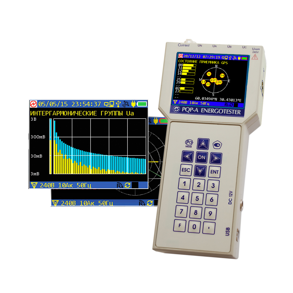
PKE-A Energy Tester
The devices are designed for:
measurements and registration of the main indicators of the quality of electrical energy established by GOST 32144-2013 (GOST R 54149-2010) with registration of protocols according to GOST 33073-2014;
measurements and registration of the main parameters of electrical energy in single-phase and three-phase electrical networks (including the effective values of voltages and currents with sinusoidal and distorted curves; active, reactive and full electrical power);
measurements of parameters of secondary circuits (load capacity of measuring transformers and voltage drop) in electric energy metering systems and electric energy losses in power supply lines.
functional test and verification of connection of meters of active and reactive power and energy, energy measuring converters of voltage, current at the places of their operation;
functional test and verification of the connection of single-phase and three-phase electric energy meters without breaking current circuits to detect theft of electricity;
measurements of electricity losses in the power supply line.
The PKE-A energy tester provides registration with subsequent transfer to a personal computer (PC) of statistical data on the PKE:
Values of the PCE according to GOST 30804.4.30 (GOST P 51317.4.30) and GOST 30804.4.7 (GOST P 51317.4.7) with a registration depth of 512 days;
Values and durations of voltage dips and overvoltages;
Values of the short-term dose of flicker;
Parameters of the electrical network and vector diagrams with the depth of registration:
- 24 hours for averaging time of 3 s,
- 200 days for averaging time of 10 min.
The program "Energy Monitoring ES" provides the formation of quality control protocols in the form of GOST 33073-2014.
Marsenergo
Saint Petersburg
Produced in: Saint Petersburg
