Catalog
Search
213 products
View:
- Selected: 1Areas of use
- Selected: 0Item names
- Selected: 0Manufacturer
- Selected: 0Made in
- Selected: 0Additional
View:
213 products
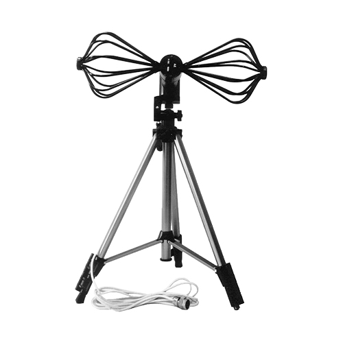
Antenna dipole P6-52
The antenna is passive.
It can be operated indoors and outdoors.
NNPO im. M.V.Frunze
Nizhny Novgorod
Produced in: Nizhny Novgorod
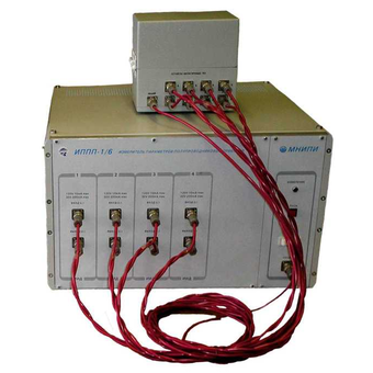
IPPP-1 Semiconductor Device Parameter Meters
Technical specifications:
4-channel automated system for measuring the parameters of semiconductors (including test structures on plates)
Study of the VAC of 2, 3, 4-pole
Parameters of each channel Source/meter:- U: ±2 V, ±30 V (200 mA),
±120 V (±10 mA), I: ±20, ±200 nA, ±2, ±20, ±200 Ma, ±2, ±10mA, (±120V), ±20,
±200 mA (±30V)
Source and meter error U, I ± 0.5%
Sensitivity of the U/I meter: 10 mv/ 0.1 pA
Graphs, tables, texts, databases
RS-232C interface, computer software
Dimensions, weight: 450x266x444 mm, 23 kg
Power supply: ~220V, 120 VA
MNIPI
Minsk
Produced in: Belarus, Minsk
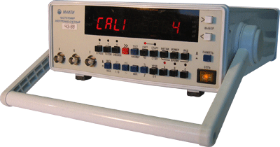
Frequency meters H3-88
Designed for measuring the frequency and period of sinusoidal and pulse signals, measuring pulse duration, time intervals, pulse duty cycle, frequency ratio of electrical signals, counting the number of pulses, output of reference frequency signals.
Technical specifications:
Input to (sinusoidal signal) - range 100 - 2500 MHz
Input A, C (sine, pulse) - range 0.01 - 200 MHz
Counting time: input A, C – 1, 10, 102, 103, 104 ms; login to – (16•1), (16•10), (16•102), (16•103), (16•104) ms
The number of averages. the period of the. vx. signal - 1, 10, 102, 103, 104
Timestamp period – 10-7, 10-6, 10-5, 10-4, 10-3
Borehole measurement at inputs A, C – 1.000001- 999999999
Frequency ratio in channels: A/S and C/A - 0.0001- 999999999; B/S - 0.5 – 999999999
Quartz thermostatic generator
The nominal frequency value is 5 MHz
Error: ± 5•10-8 - for 30 days, ± 10-7 - for 12 months
9 decimal places
Overall dimensions (HXHL) - 285x106x345 mm
Weight: 4 kg
Reference generator: 1x10⁻⁷ for 12 months.
Operating conditions: - 10° C ... +50° C
MNIPI
Minsk
Produced in: Belarus, Minsk
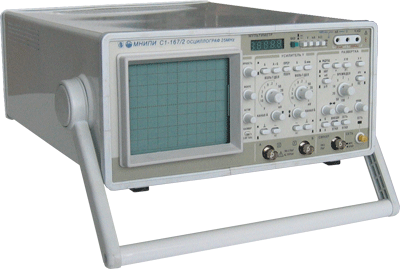
Digital oscilloscope C8-43
It is designed to study periodic signals in the frequency band 0-50 MHz and single electrical signals by registering them in digital memory with a sampling frequency of up to 50 MHz, observing their shape on a liquid crystal display (LCD), measuring the amplitude and time parameters of the signal under study.
Description:
2 mV...10 V/div; 10 ns...100 s/del
ADC: 2 channels, 100 MHz, 8 bits, 64 KB/channel
Equivalent sampling rate of 10 GHz
Marker measurements U: ±2.5%,T: ±1.5%
Pre-start, averaging,filtering
Familiar management interface
High-quality, "live" image
Additional modes in the "MENU"
Low price
Screen 80x100 mm (CRT made in Holland)
Dimensions, weight: 120x300x380 mm, 7 kg
Power supply: ~220V, 80 VA
MNIPI
Minsk
Produced in: Belarus, Minsk
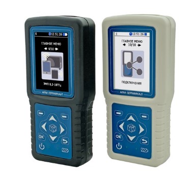
NTM-Terminal Control unit and display of measurement results
from
44 000 ₽
The NTM-Terminal block is a multifunctional device that allows you to choose:
the necessary antenna-converter,
operating mode,
measurement procedure in relation to the object of examination,
recording of measurement results.
NMT-ZASHCHITA
Moscow
Produced in: Moscow
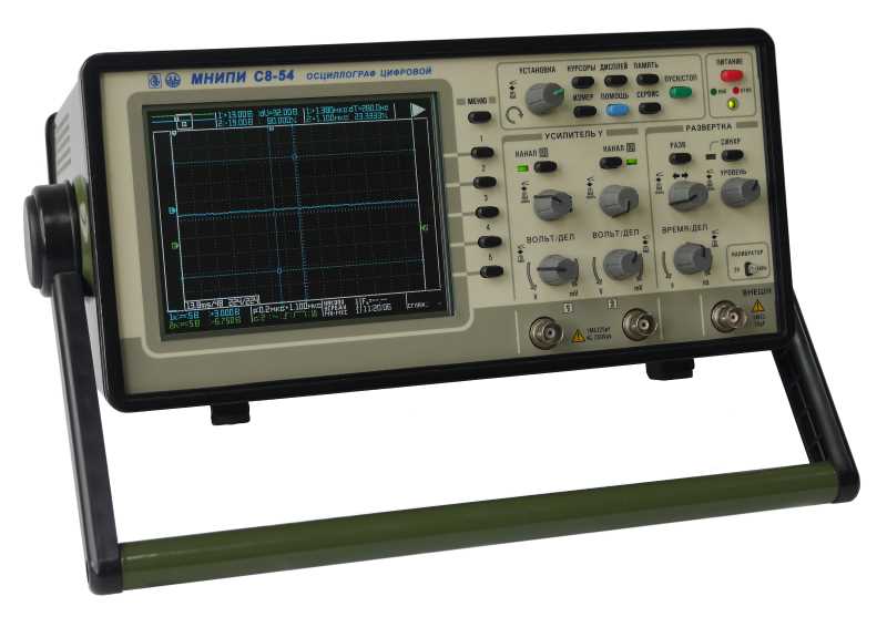
Digital oscilloscopes S8-54
Designed to study and measure the parameters of electrical signals in the frequency band from 0 to 200 MHz.
Description:
200 MHz bandwidth
2 channels, external synchronization input
Vertical sensitivity 2 mV/div
Sampling rate up to 400 Mbps, in real time
Color LCD screen with LED backlight
Saving signals on external media in graphic and text form
Cursor measurements and 22 types of digital measurements
USB and Ethernet interface
Frequency meter function
Logger function.
MNIPI
Minsk
Produced in: Belarus, Minsk
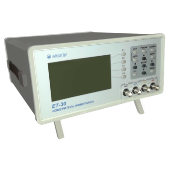
Immitance meter E7-30
Technical specifications:
Wide frequency range 25 Hz–3 MHz
Capacity (10-15-1) F
Inductance (10-11-104) Gn
Resistance (10-5-109) Ohms
Conductivity (10-11-10) Cm
Modulus of complex resistance (10-5-109) ohms
Reactance (10-5-109) Om
Phase shift angle -90° – +90°
Q factor, loss factor 10-4-104
Leakage current (10-8-10-2) A
The error is ±0.1%
Offset voltage 0 – 40 V (external up to 120 V)
Measuring signal level (0.005 – 1) V
RS-232C, USB 2.0
interfaces Mathematical processing of measurements
Dimensions, weight: 134x270x320 mm, 4 kg
Power supply ~230 V, 20 VA
MNIPI
Minsk
Produced in: Belarus, Minsk
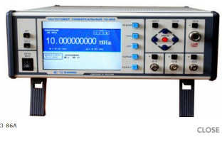
Universal frequency meter Ch3-86A
The frequency meter is capable of operating both independently and as part of automated measuring systems with an interface such as USB, RS-232 or IEEE-488 (CPC).
Technical specifications
Frequency and period of sinusoidal and video pulse signals (input A) 0.005 Hz - 100 MHz
Frequency of sinusoidal and video pulse signals (input to) 0.01 Hz - 100 MHz
Frequency of continuous sinusoidal oscillations (input C) (0.1 - 1) GHz
Frequency of continuous sinusoidal oscillations (input D) (0.6 - 17.85) GHz
Pulse duration 10 ns - 10000 s
The duration of the front, the decay of the pulses is 5 ns - 100 microseconds
Time interval from 0 to 10000 s
The frequency ratio of the two signals is up to 109
The average value of the carrier frequency of the pulse-modulated (IM) signal (input D) (0.6 - 17.85) GHz
Frequency measurement resolution 2x10⁻¹⁰ s/Rng
Phase difference of two synchronous sinusoidal signals from minus 180° to 180°
Measurement error of the phase difference of two synchronous sinusoidal signals ± 0.36° (from 1 kHz to 1 MHz)±3.6° (above 1 MHz)
Input signal level:
•for sinusoidal signal (inputs A, B) (0.03 - 7.0) V
•for video pulse signal (inputs A, B) (0.1 - 10.0) V
•for a sinusoidal signal (input C) (0.03 - 1.0) V
•for sinusoidal and IM signals (input D) 30 MW - 5 MW
Input resistance
•Inputs A, B (50±2.5) ohms; (1±0.1) MOm/100 pF
•inputs C, D (50±2.5) ohms
Nominal frequency value of the reference quartz oscillator 10 MHz
Relative error in the frequency of the quartz oscillator, no more than ± 2x10⁻⁷ in 12 months
Operating temperature range from minus 10 to 50 °C
AC power supply 220 V, 50 Hz; 220 V, 400 Hz
Power consumption, no more than 50 VA
Overall dimensions, mm 229x136x435.5
Weight, not more than 7.5 kg
TEKHNOYAKS
Moscow
Produced in: Moscow
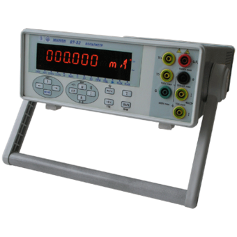
Voltmeter V7-82
Technical specifications:
DC voltage ,
Measuring range, 10 mv-1000V
Measurement error, ± 0.01%
AC voltage ,
Measuring range, 1 mV - 700 V
Measurement error, ± 0.4%
Frequency range, 20 Hz- 1 MHz
Direct current ,
Measuring range, 0.2 µA - 10 A
Measurement error, ± 0.15%
MNIPI
Minsk
Produced in: Belarus, Minsk
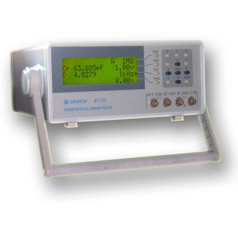
Immitance meter E7-20
Technical specifications:
Wide frequency range 25 Hz–1 MHz
Capacity (10-15-1) F
Inductance (10-11-104) Gn
Resistance (10-5-109) Ohms
Conductivity (10-11-10) Cm
Modulus of complex resistance (10-5-109) ohms
Reactance (10-5-109) Om
Phase shift angle -90° – +90°
Q factor, loss factor 10-4-104
Leakage current (10-8-10-2) A
The error is ±0.1%
Offset voltage 0 – 40 V (external up to 120 V)
Measuring signal level (0.04 – 1) V
RS-232C interface
Mathematical processing of measurements
Dimensions, weight: 127x298x300 mm, 4 kg
Power supply ~220 V, 20 VA
MNIPI
Minsk
Produced in: Belarus, Minsk
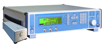
High-frequency signal generator G4-235, G4-236
Created on the basis of the G4-230 generator. Remote frequency converters extend the frequency ranges up to 53.57 GHz (G4-235) and up to 78.33 GHz (G4-236).
The generators are capable of operating both independently and as part of automated measuring systems with USB and IEEE-488 (CPC) interfaces.
Technical specifications
The frequency range at the output of the base unit is from 5 to 20 GHz
Frequency range at the output of the frequency converter (G4-235) from 37.5 to 53.57 GHz
The frequency range at the output of the frequency converter (G4-236) is from 53.57 to 78.33 GHz
Frequency tuning discreteness 0.001 Hz
The main error of the frequency setting is ± 3x10⁻⁷ Hz
The range of setting the signal power level at the output of the base unit is from minus 110 to 13 dBm
The range of setting the signal power level at the output of the frequency converter (G4-235) is from 0 to 13 dBm
The range of setting the signal power level at the output of the frequency converter (G4-236) from 0 to 10 dBm
The basic error of setting the reference power level is ± (1.0 – 2.5) dB
Metrological characteristics of the generator in FM operation mode:
- frequency range of the modulating signal from 1 Hz to 20 kHz
- frequency deviation setting range (taking into account the carrier frequency value) from 1 Hz to 200 kHz
- the main error of the frequency deviation setting is ± (5 – 18)%
Metrological characteristics of the generator in AM operation mode:
- frequency range of the modulating signal from 0.05 to 5.0 kHz
- the range of setting the amplitude modulation coefficient from 1 to 50 %
- the basic error of setting the amplitude modulation coefficient ± (0.15 M + 0.2)%
Metrological characteristics of the generator in the IM operation mode:
- the duration range of modulating pulses from 100 ns to 20 s
- the range of the modulating pulse repetition period from 140 ns to 30 s
- the difference in the duration of the output RF pulses from the duration of the modulating pulses ± 100 ns
Operating temperature range from 5°C to 40 °C
AC power supply 220 V, 50 Hz
Power consumption, no more than 150 VA
Overall dimensions, mm 498x136x487
Weight, not more than 20 kg
TEKHNOYAKS
Moscow
Produced in: Moscow
Oscilloscope S1-176
It is intended for the study of periodic electrical signals by visual observation and measurement of their amplitude and time parameters on the scale of the CRT screen in the frequency band 0-50 MHz, as well as for monitoring the parameters of two- and three-pole devices using a component tester.
Technical specifications:
Number of channels 2
Bandwidth 0 - 50 MHz
Deviation coefficients of 2 mV/div - 20 V/div (step1-2-5)
Installation error ± 3%, ± 4% with a 1:10 divider
Rise time of PH <= 7 nsec
Input impedance is 1 mOhm/25 pF, with a divider of 1:10 - 10 mOhm/23 pF
Harsh operating conditions (-10°C to +40°C)
Bandwidth 0 - 50 MHz
Two channels
Indication of deviation and sweep coefficients on LED matrices
Tenfold stretching of the sweep
Calibrator 0.6 V, 1 kHz (± 1%)
X-Y mode
Built-in Component Tester
Screen 80x100 mm
Weight 6,8 kg
MNIPI
Minsk
Produced in: Belarus, Minsk
