Catalog
Search
213 products
View:
- Selected: 1Areas of use
- Selected: 0Item names
- Selected: 0Manufacturer
- Selected: 0Made in
- Selected: 0Additional
View:
213 products
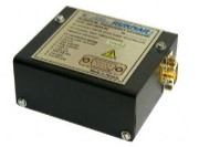
Rubidium frequency standard H1-1022
Rubidium frequency standards H1-1022 are available both in the standard version and with various options that have differences in functionality and technical characteristics:
option 01 is a device with high short–term stability of the output signal frequency;
option 02 – a device with a low-level phase noise in the output signal spectrum;
option 03 – the device has a binding module in its composition, which allows automatic correction of the frequency of the output signal according to the signal of the external time scale;
option 04 – the device has a synthesizer module in its composition, which allows you to receive a sinusoidal signal of a given frequency at the output of the device in the range from 100 Hz to 100 MHz in steps of the order of 4 × 10⁻⁶ Hz;
option 05 is a device with an extended range of ambient operating temperatures.
Through the built-in RS-232 interface, telemetry information is collected from the device nodes, and commands to change the frequency of the output signal are transmitted.
The H1-1022 frequency standards have no domestic analogues in terms of their small dimensions, weight, power consumption and operating time, as well as in terms of their numerous functional capabilities.
Ruknar
Nizhny Novgorod
Produced in: Nizhny Novgorod
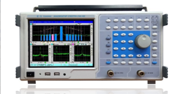
Spectrum Analyzer SK4-105
The spectrum analyzer is capable of working both independently and as part of automated measuring systems with USB and ETHERNET interfaces.
Technical specifications
Frequency range from 9 kHz to 20 GHz
The basic error of frequency measurement is ± (3-10'7hG + 0.2 Hz)
Viewing bands 0; 10 Hz - 20 GHz
Bandwidth minus 3 dB from 1 Hz to 8 MHz
Self-noise level from minus 156 to 145 dB MW/Hz
The basic level measurement error is ± (1.2-1.8) dB
The relative level of interference caused by intermodulation distortions of the 3rd order from minus 50 to 65 dB
The relative level of interference caused by combination distortions from minus 60 to 80 dB
Amplitude scales linear, quadratic, logarithmic (0.1- 20) dB/div
The frequency range of the tracking generator is from 1 MHz to 8 GHz
Operating temperature range from 5 to 40 °C
AC power supply 220 V, 50 Hz
Power consumption, no more than 85 VA
Overall dimensions, mm 420x213x172
Weight, not more than 8 kg
TEKHNOYAKS
Moscow
Produced in: Moscow
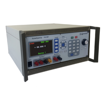
Universal calibrator H4-301
Technical specifications:
Voltage reproduction range Uk 200 mV 0.07 + 0.01
DC: from 50 MV to 600 V, Uk 2 V 0.05 + 0.005
sub-bands (Uk) 200 mV; 2; 20; 200; 600 V Uk 20 V 0.05 + 0.005
Basic error, ± (% of U + % of Uk): Uk 200 V 0.07 + 0.01
Uk 600 V 0.1 + 0.02
Voltage reproduction range UK 200 mV 0.2 + 0.05
AC: from 1 mV to 600 V, Uk 2; 20 V 0.15 + 0.02
sub-bands (Uk) 200 mV; 2; 20; 200; 600 V from 20 Hz to 20 kHz
Basic error, ± (% of U + % of Uk): sv. 20 to 40 kHz 0.2 + 0.1
Uk 200 V; 600 V:
from 40 Hz to 1 kHz 0.2 + 0.05
Power reproduction range Ik 200 Ma 0.1 + 0.02
DC: from 1 Ma to 5 A, Ik 2; 20; 200 mA 0.1 + 0.01
sub-bands (Ik) 200 Ma; 2; 20; 200 mA; 2; 5 A Ik 2 A; 5 A 0.1 + 0.02
Basic error, ± (% of I + % of Ic):
AC power reproduction range: from 10 Ma to 5 A
sub-bands (Ic) 200 Ma; 2; 20; 200 mA; 2; 5 A 0.15 + 0.05
Frequency range from 20 Hz to 1 kHz
Basic error, ± (% of I + % of Ic):
USB interface
Operating temperature range from minus 10 °C to + 50 °C
Dimensions; weight 420×342×184.5 mm; 10 kg
MNIPI
Minsk
Produced in: Belarus, Minsk
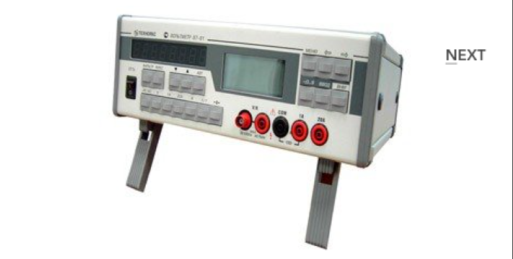
Universal voltmeter V7-81
The voltmeter is capable of operating both independently and as part of automated measuring systems with RS-232 type interfaces.
Technical specifications
Ranges of measurement of electrical quantities:
- constant electrical voltage from 10 MV to 1000 V
- SCR of alternating electric voltage in the frequency range from 10 Hz to 10 MHz (AC) from 1 mV to 750 V
- DC current from 0.1 µA to 20 A
- SCR of alternating electric current in the frequency range from 10 Hz to 5 kHz from 10 µA to 20 A
- electrical resistance from 10 mOhm to 1 GOm
- frequency of the measured alternating electric voltage from 10 Hz to 1 MHz
Measurement errors of electrical quantities:
- constant electrical voltage ± (0.0028 - 20)%
- SCR of alternating electric voltage in the frequency range from 10 Hz to 10 MHz (AC) ± (0.09 - 15)%
- DC power ± (0.012 - 20)%
- SCR of alternating electric current in the frequency range from 10 Hz to 5 kHz ± (0.11 - 2.35) %
- electrical resistance ± (0.007 - 5.5)%
- frequency of the measured alternating electric voltage ± (0.1 -10.1)%
General characteristics:
Operating temperature range from 5 to 40 °C
AC power supply 220 V, 50 Hz
Power consumption, no more than 20 VA
Overall dimensions, mm 291x110x308
Weight, not more than 4.5 kg
TEKHNOYAKS
Moscow
Produced in: Moscow
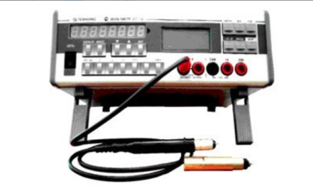
Universal voltmeter V7-79
The voltmeter is capable of operating both independently and as part of automated measuring systems with RS-232 interfaces.
Technical specifications
Measuring ranges of electrical quantities:
- constant electrical voltage from 10 MV to 1000 V
- SCR of alternating electric voltage in the frequency range from 10 Hz to 10 MHz (AC) from 1 mV to 750 V
- RF RF AC voltage in the frequency range from 10 kHz to 1500 MHz (RF) from 10 mV to 1000 V
- DC electric current from 0.1 µA to 20 A
- SCZ of alternating electric current in the frequency range from 10 Hz to 5 kHz from 10 µA to 20 A
- electrical resistance from 10 mOhm to 1 GOm
- frequency of the measured AC voltage from 10 Hz to 1 MHz
Measurement errors of electrical quantities:
- constant electrical voltage ± (0.0028 - 20)%
- SCR of alternating electric voltage in the frequency range from 10 Hz to 10 MHz (AC) ± (0.09 - 15)%
- RF RF AC voltage in the frequency range from 10 kHz to 1500 MHz (RF) ± (1.6 - 66)%
- DC current ± (0.012 - 20)%
- SCR of alternating electric current in the frequency range from 10 Hz to 5 kHz ± (0.11 - 2.35)%
- electrical resistance ± (0.007 - 5.5) %
- frequency of the measured alternating electric voltage ± (0.1 -10.1) %
General characteristics:
Operating temperature range from 5 to 40 °C
AC power supply 220 V, 50 Hz
Power consumption, no more than 20 VA
Overall dimensions, mm 291x110x308
Weight, not more than 4.5 kg
TEKHNOYAKS
Moscow
Produced in: Moscow
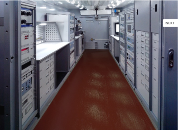
Universal mobile complex for verification and repair of measuring instruments
The complex is equipped with air conditioning, heating and ventilation systems to create and maintain a set temperature level
(20-25) ° C in the container body, at an outdoor temperature from minus 40 ° C to 40 ° C.
Operating conditions
Ambient air temperature from minus 40 to 40 ° C;
Relative humidity up to 95 % at tº= 30 ° C;
Atmospheric pressure from 84.0 to 106.7 kPa (from 630 to 800 mm Hg);
General-purpose power supply: alternating three-phase current with a frequency of (50 ± 1) Hz with a RMS voltage value in each phase (380 ± 38) V.
A set of functionally related working standards, special equipment and automation tools allows you to implement complex metrological maintenance of measuring instruments at automated (automated) and non-automated (RM) workplaces
TEKHNOYAKS
Moscow
Produced in: Moscow
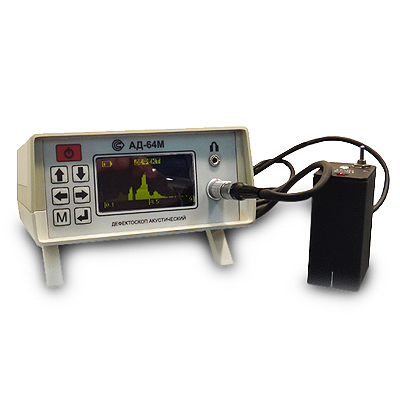
AD-64M Acoustic Impedance Flaw Detector
from
825 000 ₽
Control methods: Impedance method (IM) and free oscillation method (MSC)
Distinctive features:
- A wide range of controlled materials: from steel to foam and structures with soft external and internal elements
- Application of two complementary control methods
- One-way access
- Dry contact of the transducers with the controlled object
- Visual representation of information
- The ability to memorize and reproduce the setting modes, which excludes the use of control samples at the workplace
Technical specifications:
The minimum area of the detected defect, cm2: 1
The depth of detected defects in fiberglass, mm: up to 12...15
Light and sound signaling of defects
Number of measurements per second: 15
Weight, kg: 1
Self-powered by batteries
Continuous battery life, h: 8
Operating temperature range, °C: -10...40
RII MNPO SPEKTR
Moscow
Produced in: Moscow
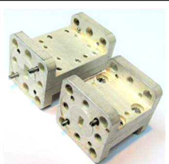
FNCH-53
These LFS can be used in conjunction with waveguide bandpass filters to increase the suppression of spurious signals and expand the upper band of the barrier.
Basic properties
Low bandwidth losses;
A wide barrage strip.
Operating conditions
Operating temperature range from minus 10
up to 50 ° C;
The relative humidity of the air is up to 98% at a temperature of 25 ° C.
Technical specifications
Waveguide cross section, mm 5.2×2.6
Bandwidth Fh-Fb at the level of -1 dB, GHz 45-53.6
The barrage band at the level of -30 dB, GHz 60-78
Bandwidth loss, 0.5-1.0 dB
TEKHNOYAKS
Moscow
Produced in: Moscow
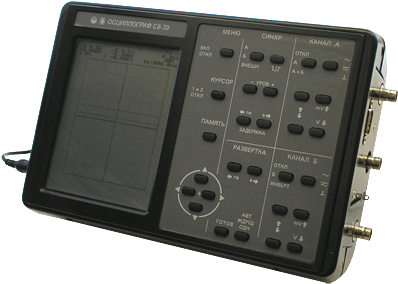
Digital oscilloscope C8-39
It is designed to study periodic signals in the frequency band 0-50 MHz and single electrical signals by registering them in digital memory with a sampling frequency of up to 50 MHz, observing their shape on a liquid crystal display (LCD), measuring the amplitude and time parameters of the signal under study.
Technical specifications:
Vertical deviation :2
Number of channels 0-50 MHz
Rise time of PH ≤ 7.0 ns
Input impedance 1 ± 0.03 mOhm, 25 pF
Deviation coefficients of 5 mV/div - 2 V/div (step 1-2-5)
The maximum input voltage is 100 V
With a divider of 1:10 250 V
The error of amplitude measurements is a≤ 2 %
5 mV...2 V; 10 ns...2 s/del.
ADC: 2 channels, 50 MHz, 8 bits
Equivalent sampling rate of 2.5 GHz
Marker measurements U: ±2.5%, T: ±1.5%
Pre-launch 8 screens,
post-launch 150 screens
Simultaneous observation of 2 signals
Cursor measurements DU and DT
Averaging modes and automatic DU and DT measurements
LCD screen - 320x240 dots (monochrome)
RS 232C interface
Dimensions, weight 176x280x80 mm, 3 kg
Power supply: +12V, 230B
MNIPI
Minsk
Produced in: Belarus, Minsk
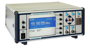
Universal frequency meter Ch3-95
The frequency meter is capable of operating both autonomously and as part of automated measuring systems with interfaces such as BUSB, RS-232, ETNET and IEEE-488 (CPC).
Technical specifications
Frequency and period of sinusoidal signals (inputs A, B) 0.001 Hz - 300 MHz
Frequency and period of video pulse signals (inputs A, B) 0.001 Hz - 300 MHz
Frequency of continuous sinusoidal oscillations (input C) (37.5 – 78.33) GHz
Pulse duration 5 ns - 1000 s
The duration of the front, the decay of the pulses is 5 ns - 100 microseconds
Time interval from -1000 to 1000 s
Frequency measurement resolution 2x10⁻¹⁰ s/Rng
Setting range of trigger levels (inputs A, B) from -2 to 2 V
The error of setting the trigger levels (inputs A, B) ± 0.01 V
Input signal level:
•for sinusoidal signal (inputs A, B) (0.03 - 10.0) V
•for video pulse signal (inputs A, B) (0.1 - 10.0) V
•for a sinusoidal signal (input C) 0.5 MW - 5 MW
Input resistance
•Inputs A, B (50±2.5) ohms; (1±0.1) MOm/100 pF
•Input With (50±2.5) ohms
Nominal frequency value of the reference quartz oscillator 10 MHz
Relative error in the frequency of the quartz oscillator, no more than ± 2x10⁻⁷ in 24 months
Operating temperature range from minus 10 to 40 °C
AC power supply 220 V, 50 Hz
Power consumption, not more than 100 VA
Overall dimensions, mm 299x130,5x433
Weight, not more than 8.5 kg
TEKHNOYAKS
Moscow
Produced in: Moscow
A set of measures of electrical resistance H2-2
Designed for storing and transmitting the size of a resistance unit, as well as for checking and calibration of working resistance measures and complex resistance meters with a four-pair or five-clamp connection scheme in the frequency range from DC to 10 MHz.
Description:
Each of the resistance measures H2-2 is a precision resistor, in series and in parallel to which fitting resistors are connected, placed in an aluminum housing.
The measures have a four-pole connection scheme. Four BNC type connectors (plugs) are located on the wall of the housing. The distance between the connectors is 22 mm.
In measures of 100 kOhm and 1 mOhm, it is possible to adjust the value of the time constant of the measure using a tuning capacitor.
MNIPI
Minsk
Produced in: Belarus, Minsk
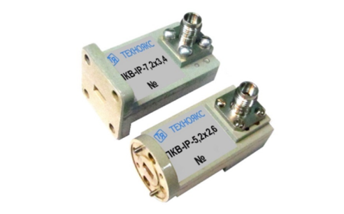
PKV-IB-5,2×2,6
Basic properties
Wide frequency range;
Small VSWR values.
Operating conditions
Operating temperature range from minus 10 to 50 ° C;
The relative humidity of the air is up to 98% at a temperature of 25 ° C.
Technical specifications
Waveguide cross section, mm 5.2×2.6
Type of coaxial connector (according to GOST RV 51914-2002) IB
Frequency range, GHz 37.50-50.00
VSWR 1.45
TEKHNOYAKS
Moscow
Produced in: Moscow
