Catalog
Metrology
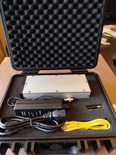
Фазометрический комплекс ФМК125
from
2500000.00
Высокоточные Бесконтактные Измерительные Системы
Nizhny Novgorod
Search
210 products
View:
- Selected: 1Areas of use
- Selected: 0Item names
- Selected: 0Manufacturer
- Selected: 0Made in
- Selected: 0Additional
View:
210 products

Frequency comparator Ch7-1014
Since it is reliable and easy to operate, the device is widely used in metrological centers, measuring laboratories, at the workplaces of REA developers.
The comparator Ch7-1014 has a communication interface with an external personal computer USB 2.0 and application software for an external PC.
At the request of the customer, the comparator can be supplied complete with a laptop or tablet computer with installed software.
Ruknar
Nizhny Novgorod
Produced in: Nizhny Novgorod
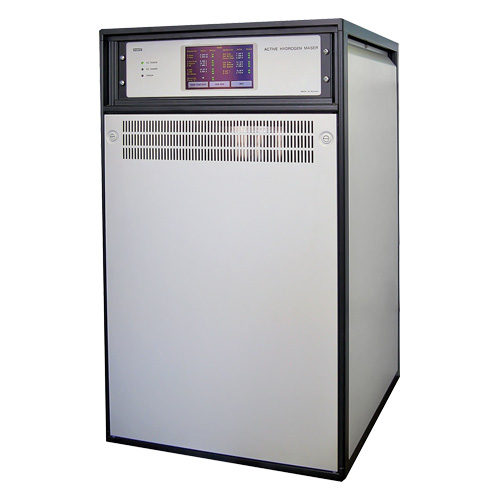
Frequency and time standard hydrogen H1-95
NNPO im. M.V.Frunze
Nizhny Novgorod
Produced in: Nizhny Novgorod Region
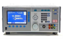
Universal calibrator H4-24
The main field of application of the calibrator is the verification of measuring instruments.
The calibrator is capable of operating both independently and as part of automated measuring systems with interfaces such as USB, RS-232, IEEE-488 and ETHERNET.
Technical specifications
Ranges of reproduction of electrical quantities:
- constant electrical voltage from 0 to 1000 V
- alternating electric voltage in the frequency range from 10 Hz to 70 kHz from 0.9 mV to 1050 V
- alternating electric voltage in the frequency range up to 100 kHz up to 750 V
- alternating electrical voltage in the frequency range up to 1 MHz to 110 V
- the power of direct electric current from 0 to 2 A
- the power of alternating electric current in the frequency range from 10 Hz to 10 kHz from 0.9 µA to 2 A
- electrical resistance of 1, 10, 100 ohms, 1,10,100 kOhm, 1,10,100 mOhm
Errors in the reproduction of electrical quantities:
- constant electrical voltage ± (0.0012 – 0.003)% of U + (0.0003 – 0.015)% of
Up - alternating electric voltage in the frequency range from 10 Hz to 1 MHz ± (0.007 – 0.3)% of U + (0.001 – 0.25)% of
Up - DC current ± (0.004 – 0.007)% of I + (0.001 – 0.01)% of
Ip - AC electric current in the frequency range from 10 Hz to 10 kHz ± (0.015 – 0.1)% of I + (0.002 – 0.1)% of
Ip - electrical resistance ± (0.002 – 0.005)%
General characteristics:
Operating temperature range from 5 to 40 °C
AC power supply 220 V, 50 Hz
Power consumption, no more than 500 VA
Overall dimensions, mm 480x200x550
Weight, not more than 35 kg
TEKHNOYAKS
Moscow
Produced in: Moscow
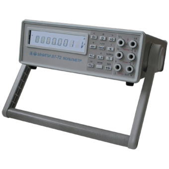
Voltmeter V7-72
Technical specifications:
DC voltage
Measuring range 2 mv-1000 V
Measurement error ± (0.001 - 0.004)%
AC voltage
Measuring range 1 mV - 700 V
Measurement error ± (0.1-8)%
Frequency range 10 Hz -1 MHz
MNIPI
Minsk
Produced in: Belarus, Minsk
IT3000 Adjustable current source up to 3.6 kA
Marsenergo
Saint Petersburg
Produced in: Saint Petersburg
High-frequency signal generator G4-232
A remote frequency converter with coaxial output extends the frequency range up to 37.5 GHz. The included coaxial-waveguide transitions and the ability to connect a small frequency converter directly to the user's device expand the scope of the device.
The generator is capable of operating both independently and as part of automated measuring systems with USB and IEEE-488 (CPC) interfaces.
Technical specifications
The frequency range at the output of the base unit is from 5 to 20 GHz
The frequency range at the output of the frequency converter is from 5 to 37.5 GHz
Frequency tuning discreteness 0.001 Hz
The main error of the frequency setting is ± 3x10⁻⁷ Hz
The range of setting the signal power level at the output of the base unit is from minus 110 to 13 dBm
The range of setting the signal power level at the output of the frequency converter is from 0 to 13 dBm
The basic error of setting the reference power level is ± (1.0 – 2.0) dB
Metrological characteristics of the generator in the FM operation mode:
- frequency range of the modulating signal:
LF from 1 Hz to 20 kHz
RF from 10 Hz to 100 kHz
- frequency deviation setting range (taking into account the carrier frequency value):
LF from 1 Hz to 200 kHz
RF from 10 Hz to 10000 kHz
- the main error of the frequency deviation setting is ± (5 – 18)%
Metrological characteristics of the generator in AM operation mode:
- frequency range of the modulating signal from 0.05 to 5.0 kHz
- the range of setting the amplitude modulation coefficient from 1 to 50 %
- the basic error of setting the amplitude modulation coefficient:
internal ± (0.15 M + 0.2)%
external ± (0.20 M + 0.5)%
Metrological characteristics of the generator in the IM operation mode:
- the duration range of modulating pulses from 100 ns to 20 s
- the range of the modulating pulse repetition period from 140 ns to 30 s
- the difference in the duration of the output RF pulses from the duration of the modulating pulses ± 100 ns
Operating temperature range from minus 10°C to 40 °C
AC power supply 220 V, 50 Hz
Power consumption, no more than 150 VA
Overall dimensions, mm 498x136x487
Weight, not more than 20 kg
TEKHNOYAKS
Moscow
Produced in: Moscow
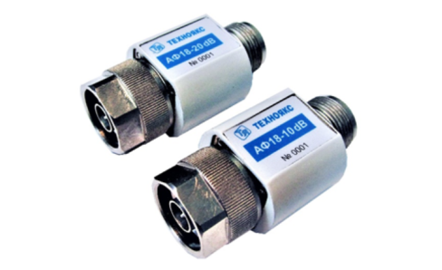
AF18-20dB
Basic properties
Wide frequency range;
Small VSWR values.
Operating conditions
Operating temperature range from minus 10 to 50 ° C;
The relative humidity of the air is up to 98% at a temperature of 25 ° C.
Technical specifications
Nominal attenuation, 20 dB
Attenuation error, dB ± 1.0
VSWR 1.4
Frequency range, GHz 0-18
Input power, W 1
Type of coaxial connectors (according to GOST RV 51914-2002) IIIB-IIIP
TEKHNOYAKS
Moscow
Produced in: Moscow
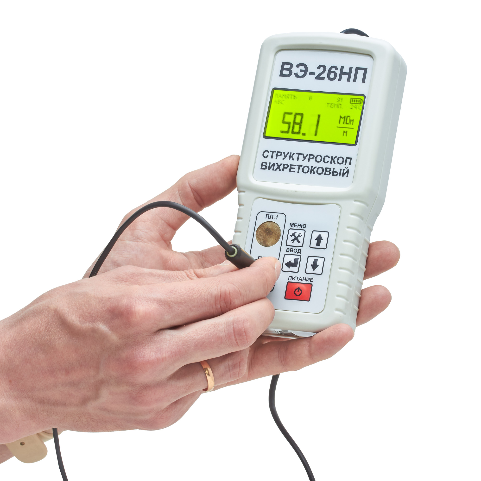
VE-26NP Eddy current structuroscope
from
195 000 ₽
Distinctive features:
The built-in thermometer allows you to take into account the influence of ambient temperature and improve the measurement accuracy. The built-in memory stores 4096 electrical conductivity measurement results for subsequent transfer to a PC.
Specifications:
Measuring range of the absolute value of specific electrical conductivity, MSm/m from 5 to 60
Measuring range of increments of electrical conductivity, MS/m from -9.99 to +9.99 Limit of permissible basic relative measurement error, % no more than 2 Permissible gap between the transducer and the surface of the controlled product, mm, no more than 0.25 Digital display of measurement results Power supply from RRZ type battery, V 9 Power consumption, mW, no more than 40 Operating temperature range, °C 5...40 Dimensions, mm 57*84*30 Weight, g 270±20
Measuring range of increments of electrical conductivity, MS/m from -9.99 to +9.99 Limit of permissible basic relative measurement error, % no more than 2 Permissible gap between the transducer and the surface of the controlled product, mm, no more than 0.25 Digital display of measurement results Power supply from RRZ type battery, V 9 Power consumption, mW, no more than 40 Operating temperature range, °C 5...40 Dimensions, mm 57*84*30 Weight, g 270±20
RII MNPO SPEKTR
Moscow
Produced in: Moscow
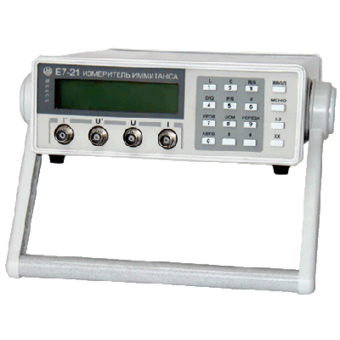
Immitance meter E7-21
Technical specifications:
Capacitance (10-13-0.02) F, inductance (10-8–16x103) Gn
Resistance (10-3–2x10⁷) ohms
Conductivity (10-9-10) Cm
Q factor, loss factor 10-3-103
The error is ±0.15%
Offset voltage 2±0.2 V
Measuring signal levels (0.1±0.02) V and (1±0.2) V
Range selection: automatic, manual
RS-232C interface
Dimensions, weight: 90x265x317 mm, 2 kg
Power supply: ~220V, 10 VA
MNIPI
Minsk
Produced in: Belarus, Minsk
Frequency comparator Ch7-1015
Since it is reliable and easy to operate, the device is widely used in metrological centers, measuring laboratories, at the workplaces of REA developers.
The memory of the comparator Ch7-1015 contains information about the main technical characteristics of domestic and foreign rubidium frequency standards presented on the Russian market, which greatly simplifies the process of checking devices in calibration laboratories.
The device has a USB 2.0 communication interface with an external personal computer and application software for an external PC.
The comparator Ch7-1015 has the ability to remotely control all modes of operation via a TCP protocol streaming socket and can work within an automated system.
Ruknar
Nizhny Novgorod
Produced in: Nizhny Novgorod
Universal calibrator H4-301/1
Technical specifications:
Voltage reproduction range Uk 200 mV 0.07 + 0.01
DC: from 50 MV to 600 V, Uk 2 V 0.05 + 0.005
sub-bands (UK) 200 MV; 2; 20; 200; 600 V Uk 20 V 0.05 + 0.005
Basic error, ± (% of U + % of Uk): Uk 200 V 0.07 + 0.01
Uk 600 V 0.1 + 0.02
Voltage reproduction range Uk 200 mV 0.2 + 0.05
AC: from 1 mV to 600 V, sv. 20 to 40 kHz 0.2 + 0.1
sub-bands (Uk) 200 mV; 2; 20; 200; 600 V Uk 2; 20 V 0.15 + 0.02
Basic error, ± (% of U + % of Uk): from 20 Hz to 20 kHz 0.15 + 0.02
Uk 200 V; 600 V: 0.2 + 0.05
from 40 Hz to 1 kHz 0.2 + 0.05
DC power reproduction range: from 1 Ma to 200 mA,
sub-bands (Ic) 200 Ma; 2; 20; 200 mA Ic 200 Ma 0.1 + 0.02
Basic error, ± (% of I + % of Ic): Ic 2; 20; 200mA 0.1 + 0.01
Power reproduction range
AC: from 10 Ma to 200 mA,
sub-ranges (Ic) 200 Ma; 2; 20; 200 mA 0.15 + 0.05
Frequency range from 20 Hz to 1 k Hz
Basic error, ± (% of I + % of Ic):
USB interface
Operating temperature range from minus 10 to +50 C
Dimensions; weight 428×327×235× mm; 10 kg
MNIPI
Minsk
Produced in: Belarus, Minsk
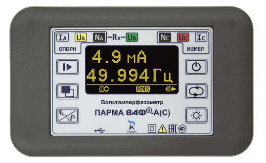
VOLTAMMETER PARMA VAF-A(C)
Scope of application
· operational maintenance of relay protection circuits and power circuits of electrical installations
· phasing during adjustment of differential protection, connection of current and voltage transformers, electric motors
· control of the correct phasing of the connection accounting circuits
· removal of the volt-ampere characteristic and measurement of angles
· monitoring of single- and three-phase circuits in power supply cabinets
PARMA
Saint Petersburg
Produced in: Saint Petersburg