Catalog
Search
728 products
View:
- Selected: 1Applying
- Selected: 0Names
- Selected: 0Manufacturer
- Selected: 0Made in
- Selected: 0Additional
View:
728 products
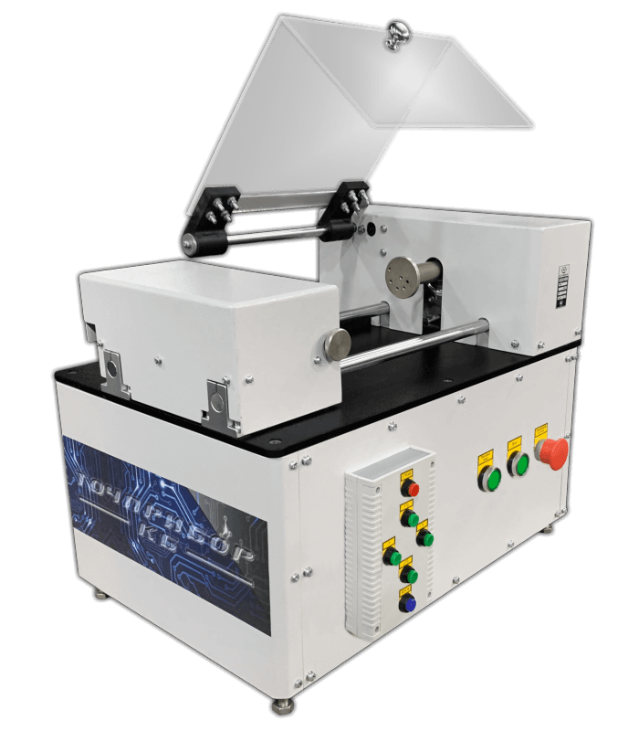
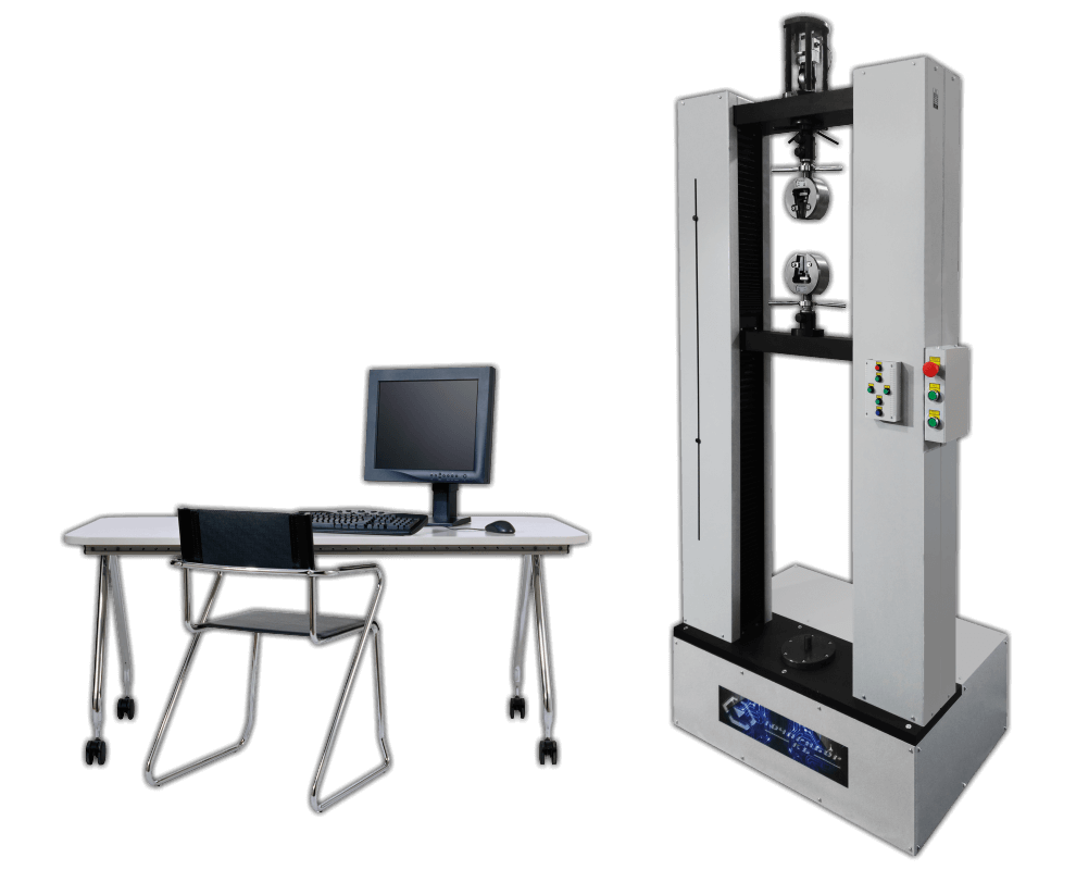
IMK-30 Torsion testing machine
Technical specifications:
Maximum load (torque): 30 N·m
Maximum twisting angle: 50000°
The discreteness of the twisting angle: 0.01°
Twisting angle error: ±0.1°
Torque discreteness: 0.001 N·m
Relative error of torque measurement: no more than 1% in the measurement range from 0.6 to 30 Nm
Torque measurement error: no more than 0.01 N·m in the measurement range from 0 to 0.6 N · m
Maximum rotation speed: 10 rpm
Weight: 150 kg
Overall dimensions (length x width x height): 1000 x 500 x 500 mm
Diameter of the universal testing device: 80 mm
Maximum spring length: 300 mm or more
Tochpribor-KB
Ivanovo
Produced in: Ivanovo
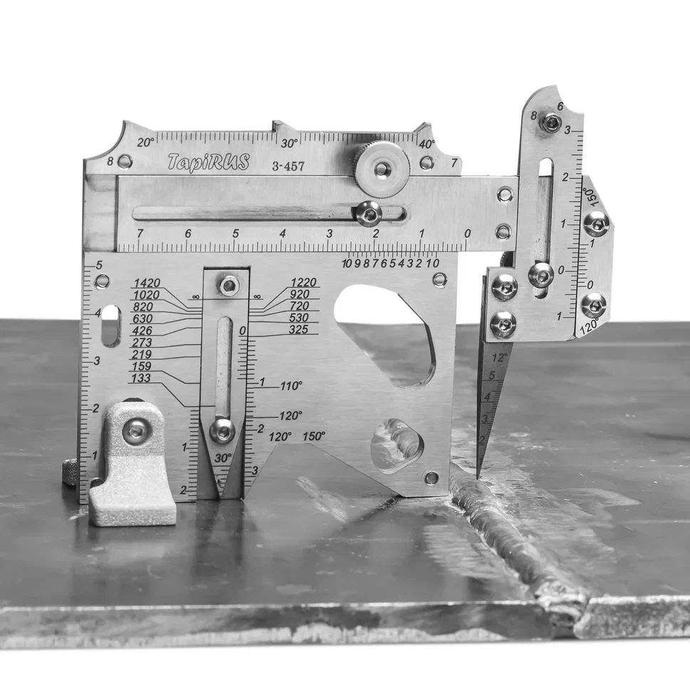
UShS "Tapirus" with cover and supports
from
18 000 ₽
The UShS TapiRus is designed to replace numerous templates and devices used in visual and measuring quality control of welded joints. It is approved as a means of measuring the geometric parameters of welded joints and surface defects during visual and measuring control (VIC) and supplied with verification. It allows you to determine most of the geometric parameters of welded joints and surface defects: the width and convexity of the seam, the depth of the cut, the amount of edge displacement, the angle of the angular seam, the angle of the bevel and the gap, etc. Equipped with supports that allow you to uniquely position the template on a curved surface. To carry out measurements with an error of 0.1 mm, scales with a vernier are applied to the TapiRUS surface. It contains a number of gauges for assessing the smooth transition from the deposited to the base metal, the size of the cathets, radii and angles of cutting edges. Equipped with a probe with a replaceable measuring needle to determine the size of gaps and heights / depressions.
The development, preparation for production and manufacture of TapiRus were carried out exclusively in digital format.
The latest laser and additive technologies are used in the production of TapiRUS:
high-precision laser cutting machines in inert gas;
five-axis CNC machining centers;
ultra-precise color laser engraving of the entire product assembled;
laser stereolithography (SLA) is a technology of layer–by-layer synthesis of a material from a liquid photopolymer.
Advantages
Easy to install. Accurate positioning along the normal to the surface of the object of control and stability of the position when performing measurements.
Functionality. Measurement of most geometric parameters of welded joints and surface defects.
Measurement accuracy. The measurement error on the template scales does not exceed 0.1 mm.
Modernity. Online calculator ergonomic accessories smart version.
More detailed information can be found on the website tapirus.info
MEASURED PARAMETERS AND DEFECTS
VIC at the stage of input control
wall thickness
depth of corrosion ulcers on the base metal
the depth of corrosion ulcers on the weld
the depth of scratches (risks), a bully on the base metal
edge bevel angle
the amount of blunting
geometric parameters of the dent
VIC during assembly (preparation for assembly)
edge offset
withdrawal (angularity) of edges
the gap in the cutting
the height of the potholders
angular displacement
VIC in the welding process (surfacing)
edge offset
height of the root (filling) layer
withdrawal (angularity) of edges
angular displacement
VIC of finished welded joints (structures)
edge offset
angular displacement
the height of the reinforcement of the seam
the height of the bulge (when welding elements of different thickness)
the width of the reinforcement of the seam
withdrawal (angularity) of edges
the depth of the sinking between the rollers
incomplete filling of the cutting edges
scaliness of the seam surface
smooth transition
undercut depth
seam crater depth
technical specifications
Measured parameter Scale Range,mm Error, mm
Depth, mm H 0...20 ±0.1 (in the range 0...10 on), ± 0.5 (in the range over 10...20)
Height, mm H 0...6 ±0.1
Width, mm W 0...55 ±0.1 (in the range 0...10 on), ± 0.5 (in the range over 10...20)
Clearance, mm N 0...5 ±0.1
Dullness, mm F, G 0...25 ±0.5
Specifications
Overall dimensions, mm, no more
(without supports) 115x85x15 ± 0.5
(with supports) 115x85x42 ±0.5
Average time to failure, cycles,
at least 55,000
Weight, kg, not more than 0.22
Average service life, at least 1 year
RII MNPO SPEKTR
Moscow
Produced in: Moscow
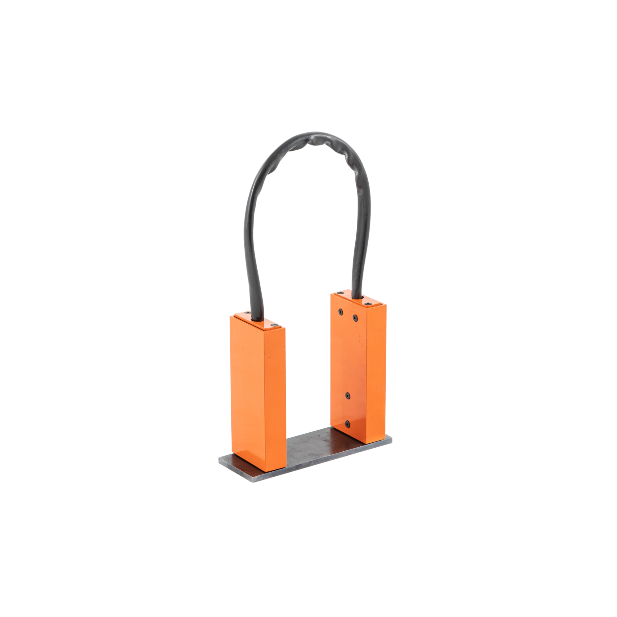
UN-5 Magnetizing device
from
83 000 ₽
The principle of operation of the magnetization device:
The device consists of two compact blocks made of non-magnetic material connected by a flexible magnetic circuit. In each block there is a permanent magnet made of neodymium-iron-boron alloy (Ne-Fe-B). When installing the blocks on the surface of the part, a closed magnetic circuit is formed with the direction of the magnetizing field from one pole to the other. Above the defect scattering fields, magnetic powder particles are deposited to form an indicator pattern.
Design features and advantages of the device for magnetic particle control UN-5
The delivery package with the device includes a portable case, an inter-pole jumper installed during transportation, and a liner for fixing blocks with permanent magnets.
The UN-5 portable device does not require electrical power and therefore can be used where the supply of stationary power is difficult or impossible under regulatory documents: in the field, when working at height, for inspection of capacitive equipment operating under pressure, etc.
- The device is easy to use, lightweight and small-sized, working with it does not require special physical and technical training from the operator;
- Flexible magnetic core allows you to use the device to control parts of complex shape;
- The UN-5 magnetizing device is distinguished by an increased quality of the indicator pattern and an increased control zone due to a reduced uncontrolled zone near the poles and an improved ratio of the normal and tangential components of the magnetic field (Russian patent No. 60732);
- The technical characteristics of the device comply with Russian and foreign regulatory documents, this being the reason of its widespread use in more than 40 countries, including Germany, France, Brazil and Norway.
When monitoring, the controlled area is the central part of the area located between the magnetic poles of the device.
The width of the monitored area is determined by the width of the magnetic poles of the device and is approximately 60 mm. The length of the monitored section depends on the inter-pole distance.
the dimensions of the controlled area are given depending on the device's inter-pole distance:
Inter-pole distance, mm 95: 75 55
Controlled area between the working poles, mm: 60x60 40x60 25x55
The length of the defect detection zone depends on the distance established between the working poles of the magnet on the controlled product.
Defects are not detected in the areas adjacent to the poles of the magnet. The length of these sections is 18 mm with an interpolar distance of 95 and 75 mm. With an interpolar distance of 55 mm these sections are 13 mm long.
Scope of application:
Magnetizing devices for magnetic powder flaw detection are used in many industries, including railway, water and aviation transport, in the construction and operation of pipelines, in chemical and petrochemical production.
The flexible link between the magnetic blocks allows the control of products of complex shape, for example, cylindrical tanks, high-pressure apparatuses, main pipelines, etc.
When checking for defects, the device can be used together with other auxiliary equipment for:
- preliminary and subsequent demagnetization;
- application of a magnetic indicator (which can be dry or in the form of an emulsion);
- magnetoluminescent control (with ultraviolet lamps).
RII MNPO SPEKTR
Moscow
Produced in: Moscow
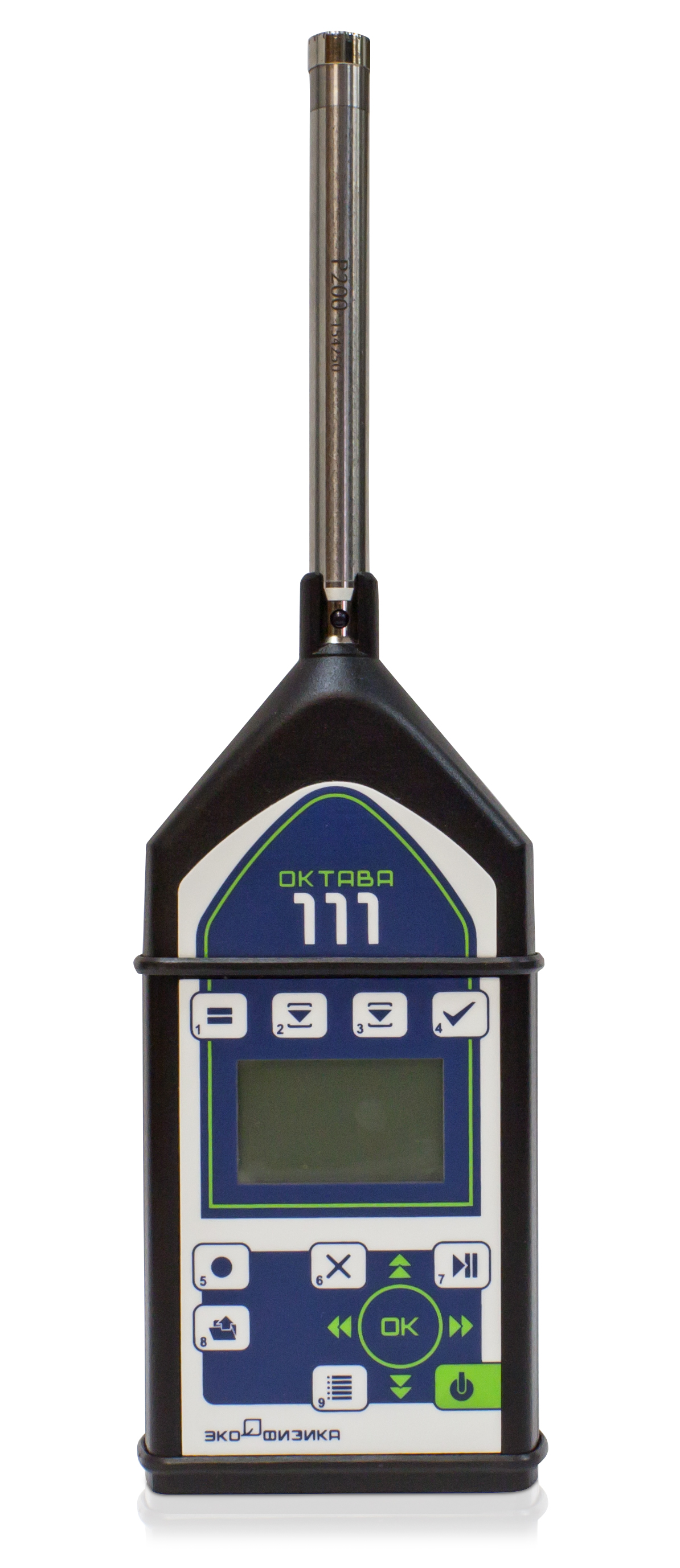
OCTAVE-111 Noise meter, spectrum analyzer
Functionality
■ Sound level measurement: Class 1 according to GOST 17187-2010, IEC 61672-1
■ Measures sound pressure levels in octave and third octave frequency bands
■ Has a metal body, resistant to external influences
■ Automatic recording of measurement results in memory
■ Non-volatile memory
■ Telemetry channel, remote control and operation of the device
Features
■ Easy setup: one measurement mode, all values are measured
simultaneously
■ Easy to manage: all results are grouped in two windows
■ Measurement of sound levels below 20 dBA
■ Affordable solution
Application areas
■ Noise control in residential and public buildings
■ Noise control on the territory of enterprises and residential buildings
■ Production control
■ Vehicle inspection
Complies with standards:
- as a noise meter: GOST 53188.1-2019 (17187-2010, IEC 61672-1), Class 1
- as a spectrum analyzer: GOST R 8.714-2010, IEC 61260 (Class 1)
Noise meter mode
- Measuring range of sound levels, dBA: from 19 to 150*
- Frequency characteristics: A, C, Z, AU, FI, G
- Time characteristics: S, F, I, Peak, Leq
* When equipped with 50 mV/Pa microphones and 12 mV/Pa
Spectrum Analyzer mode with constant relative bandwidth
- Frequency range of digital octave filters, Hz: 31.5 - 16000
- Frequency range of digital third-octave filters, Hz: 25 - 20000
PKF TSIFROVYE PRIBORY
Moscow
Produced in: Moscow
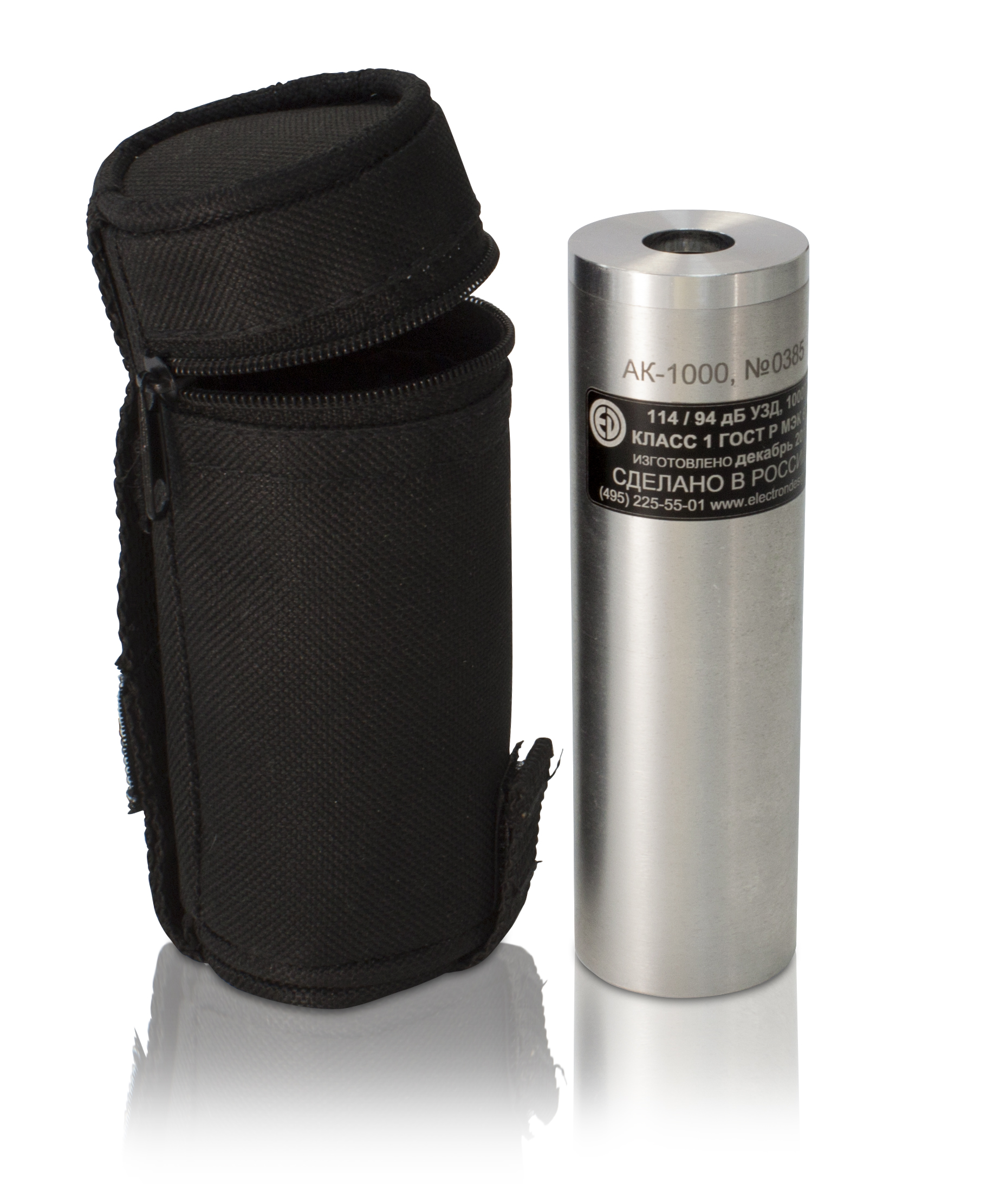
AK-1000 Acoustic calibrator
characteristics
The AK-1000 is recommended for use with OCTAVE-101A, OCTAVE-101AM, OCTAVE-110A, OCTAVE-110A-ECO, OCTAVE-121, OCTAPHONE-110, OCTAVE-201, ECOPHYSICS-110A sound meters. The AK-1000 can be used for calibration of acoustic measuring paths with VMK-205, MK-265, MR-201, M-201, MK-233 microphones, and other ½-inch microphones.
technical specifications
Reproducible ultrasound, dB (rel. 20 µPa): 94 and 114
The limits of the permissible basic error of the reproducible ultrasound, dB: ± 0.25
Limits of the permissible additional error of the ultrasound caused by a change
in ambient temperature in the operating temperature range, dB: ± 0.08
Frequency of the reproduced sound pressure, Hz: 1000
Limits of the permissible basic relative error of reproduction of the sound
pressure frequency, %: ± 0.7
Limits of the permissible additional relative error of the sound pressure frequency caused by a change in ambient temperature in the operating temperature range, %: ± 0.07
Coefficient of nonlinear distortion, %, not more than: 2.5
Weight (with batteries), kg, no more than: 0.250
Overall dimensions (length×diameter), mm, no more: 158×35
Operating conditions:
- ambient temperature, ° C: from minus 10 to 50
- relative humidity (at 40 ° C), %, not more than: 90
- atmospheric pressure, kPa: from 65 to 108
PKF TSIFROVYE PRIBORY
Moscow
Produced in: Moscow
